Ignition device and ignition method for combustor

An ignition device and burner technology, which is applied in the direction of burners, lighting and heating equipment, etc., can solve the problems of insufficient oil mist combustion, waste of energy, and generation of toxic substances, so as to improve energy utilization rate, improve combustion sufficiency, The effect of increasing the oxygen content

Inactive Publication Date: 2020-02-21
南京建安机械制造有限公司
View PDF6 Cites 1 Cited by
  • Summary
  • Abstract
  • Description
  • Claims
  • Application Information

AI Technical Summary

Problems solved by technology

[0003] The above existing technical solutions have the following defects: when the oil mist is ignited, the oxygen content around the oil mist is insufficient, resulting in insufficient combustion of the oil mist, wasting energy and causing the generation of toxic substances

Method used


Image

  • Ignition device and ignition method for combustor
  • Ignition device and ignition method for combustor

Examples


Embodiment

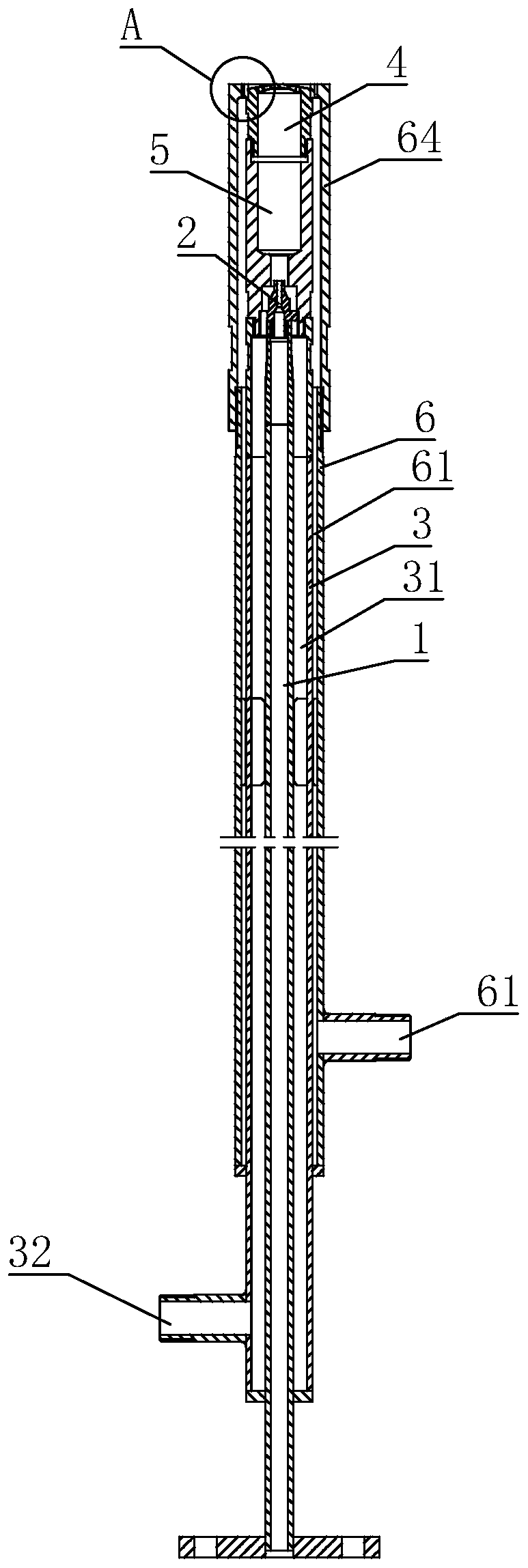
[0031] Embodiment: a kind of ignition device of burner, as figure 1 , including a round tubular oil pipe 1 and an inner air pipe 3 coaxially sleeved outside the oil pipe 1. At this time, an inner air cavity 31 is formed between the inner air pipe 3 and the oil pipe 1. One end of the oil pipe 1 is connected with a nozzle 2, and the inner air The end of the pipe 3 facing the oil nozzle 2 is set as the air outlet end, and the wall of the inner air pipe 3 away from the oil nozzle 2 is provided with a first air inlet 32 ​​. The oil pipe 1 is filled with oil, and when the oil passes through the oil nozzle 2, it is dispersed into oil mist. At this time, the operator feeds air into the first air inlet 32, and the air passes through the inner air cavity 31 and flows out from the air outlet end of the inner air pipe 3. At this time, this part of the air is mixed with the oil mist, which increases the oxygen content around the oil mist.

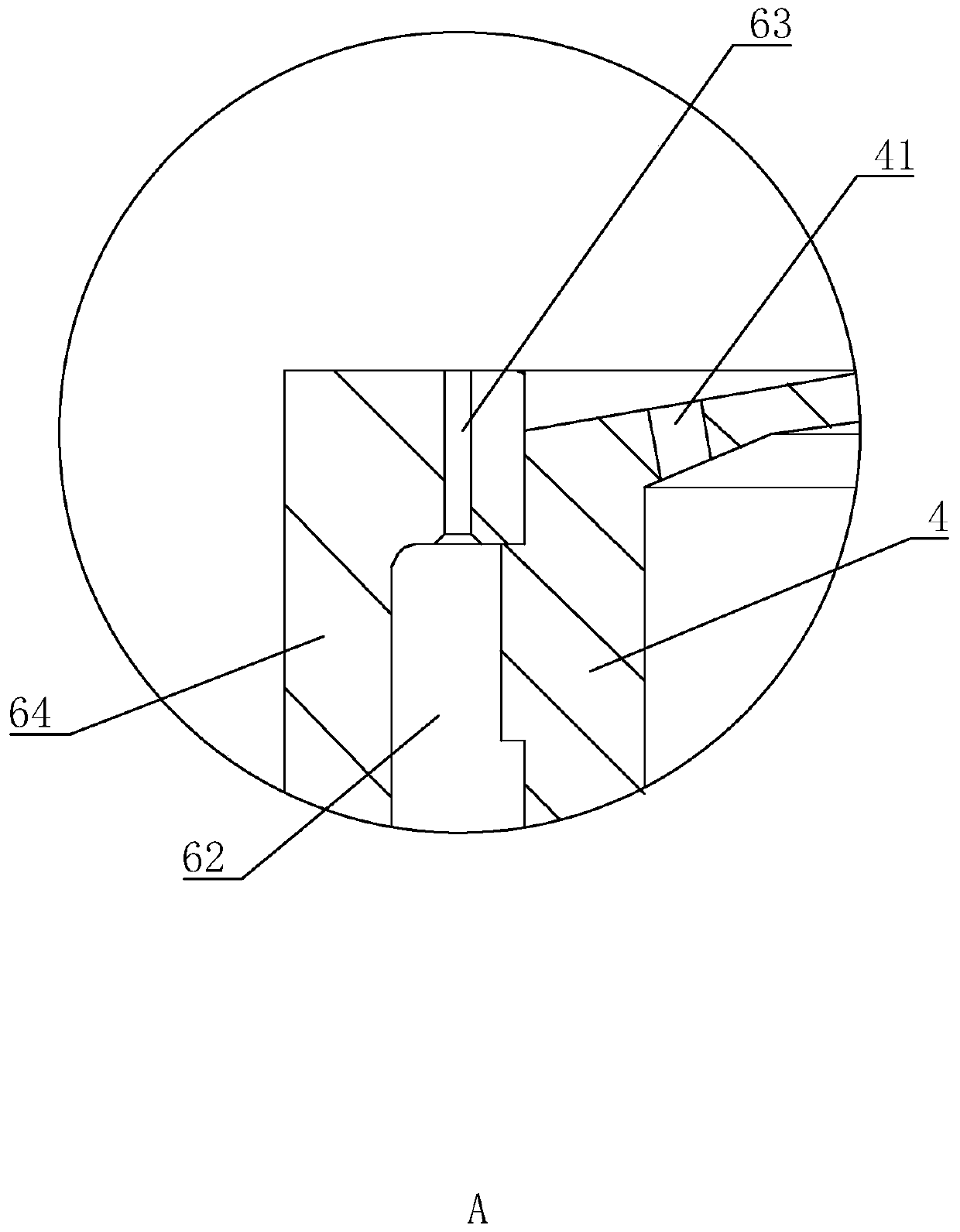
[0032] Such as figure 1 The end of the inner ai...


PUM


Abstract

The invention discloses an ignition device and ignition method for a combustor. The ignition device and ignition method for the combustor are applied to the field of combustors. The essential of the technical scheme is as follows: the ignition device for the combustor comprises a spray nozzle, an oil pipe, an oil nozzle connected to one end of the oil pipe, and an inner air pipe, wherein the innerair pipe is arranged outside the oil pipe in a sleeved manner and forms an inner air cavity with the oil pipe; a first air inlet port is formed in the inner air pipe; one end facing the oil nozzle, of the inner air pipe, is an air outlet end; the oil nozzle and the air outlet end of the inner air pipe are connected to the spray nozzle simultaneously; and a spray port is formed in the spray nozzle. The ignition device and ignition method for the combustor have the following technical effects: the oxygen content of a surrounding environment during combustion for oil mist is increased, and thenthe combustion sufficiency degree of the oil mist is increased, and the effects of energy conservation and environment protection are achieved.

Description

technical field [0001] The invention relates to the technical field of burners, in particular to an ignition device and an ignition method for a burner. Background technique [0002] At present, the ignition device of the burner on the market is usually an oil pipe plus a nozzle. After the oil passes through the oil pipe, it is atomized at the nozzle, and then this part of the oil mist is ignited to make the oil mist burn. Into the oil to ensure the continuation of the flame. [0003] The above-mentioned prior art solutions have the following defects: when the oil mist is ignited, the oxygen content around the oil mist is insufficient, resulting in insufficient combustion of the oil mist, wasting energy and generating toxic substances. Contents of the invention [0004] In view of the deficiencies in the prior art, the purpose of the present invention is to provide an ignition device for a burner, which can improve the combustion sufficiency of the oil mist, so as to achi...

Claims


Application Information

Patent Timeline
Patent Type & Authority Applications(China)
IPC IPC(8): F23D11/38F23D11/40
CPCF23D11/38F23D11/40
Inventor 周竹锦
Owner 南京建安机械制造有限公司
Why Eureka
Try Eureka