Heat conduction pipe and electronic equipment

A technology of electronic equipment and heat pipe, which is applied in the field of electronic equipment, can solve the problems of heat pipe vacuum chamber changes, heat pipe deformation and other problems

Inactive Publication Date: 2020-02-21
VIVO MOBILE COMM CO LTD
View PDF5 Cites 1 Cited by
  • Summary
  • Abstract
  • Description
  • Claims
  • Application Information

AI Technical Summary

Problems solved by technology

[0005] In view of this, the embodiments of the present invention provide a heat pipe and electronic equipment to solve the problem th

Method used


Image

  • Heat conduction pipe and electronic equipment
  • Heat conduction pipe and electronic equipment
  • Heat conduction pipe and electronic equipment

Examples


Embodiment Construction

[0019] The following will clearly and completely describe the technical solutions in the embodiments of the present invention with reference to the accompanying drawings in the embodiments of the present invention. Obviously, the described embodiments are only some, not all, embodiments of the present invention. Based on the embodiments of the present invention, all other embodiments obtained by persons of ordinary skill in the art without making creative efforts belong to the protection scope of the present invention.

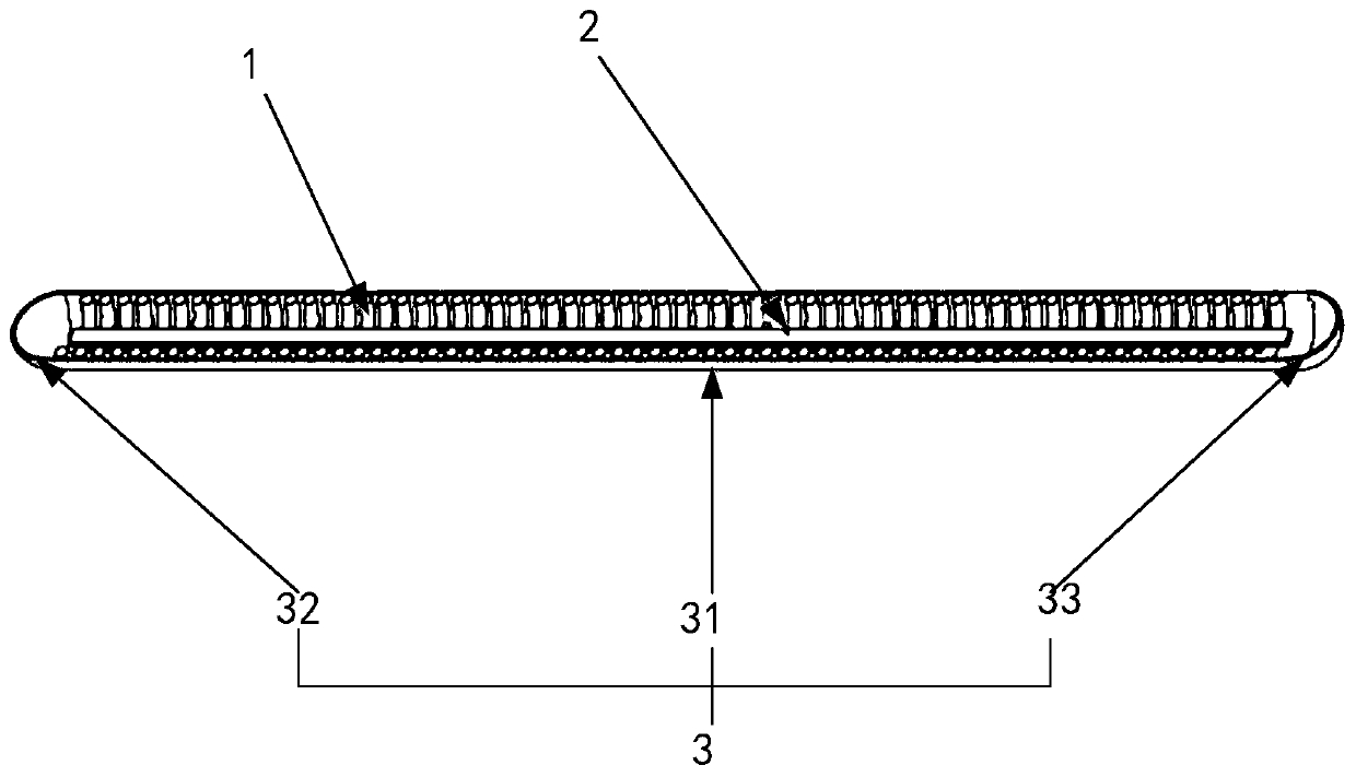
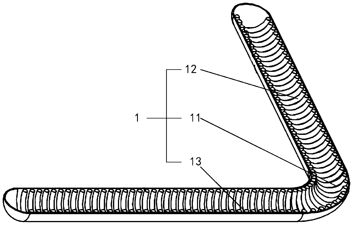
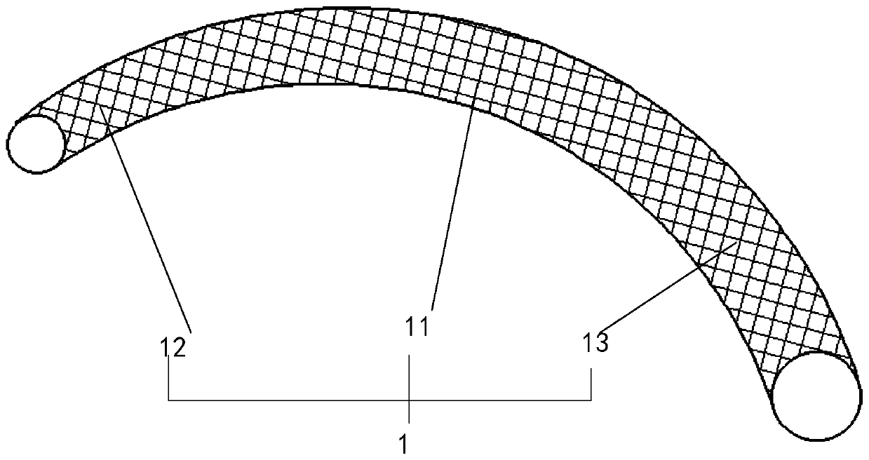
[0020] The heat pipe according to the embodiment of the present invention will be described in detail below with reference to the accompanying drawings. figure 1 It is a structural schematic diagram of the heat pipe of the embodiment of the present invention. Such as figure 1 As shown, the heat pipe includes a flexible pipe 1, a liquid-absorbing core 2 and a sealing film 3; the liquid-absorbing core 2 is fixed inside the flexible pipe 1, and the liquid-absorb...


PUM


Abstract

The embodiment of the invention provides a heat conduction pipe and electronic equipment. The heat conduction pipe comprises a flexible pipe, a liquid absorption core and a sealing film, wherein the liquid absorption core is fixed to the interior of the flexible pipe and is filled with liquid; the sealing film comprises a second sealing part and a third sealing part which are respectively fixed tothe two ends of a first sealing part; and the flexible pipe is sleeved with the first sealing part, and nozzles at the two ends of the flexible pipe are respectively covered with the second sealing part and the third sealing part, so that a sealed cavity is formed inside the flexible pipe. Therefore, after the flexible pipe is sleeved with the sealing film, the flexible pipe is one of bendable pipe bodies, the bendable pipe body is an elastomer, and the liquid absorption core can also be bent at the same time, so that the heat conduction pipe is restored to the original shape after being deformed by external force, the cavity inside the heat conduction pipe is not changed all the time, the steam flow inside the heat conduction pipe is not influenced, and the heat conduction pipe is not broken with the reverse folding of a display screen folding mechanism of the electronic equipment.

Description

technical field [0001] The invention relates to the technical field of electronic equipment, in particular to a heat pipe and electronic equipment. Background technique [0002] As a high-efficiency heat transfer device, heat pipes are widely used in various electronic equipment, such as communication equipment such as servers, base stations, and electronic equipment. When the heat pipe is applied in an electronic device, it has a particularly obvious effect on the heat dissipation of the electronic device. [0003] At present, heat pipes are usually composed of copper pipes and wicks. The wick is fixed in the inner cavity of the copper tube. One end of the heat pipe is the evaporation end, and the other end is the condensation end. When the evaporating end is heated, the liquid in the liquid-absorbing core evaporates rapidly, and the steam flows from the evaporating end to the condensing end under the action of the pressure difference generated by the temperature differe...

Claims


Application Information

Patent Timeline
IPC IPC(8): F28D15/02F28D15/04H05K7/20
CPCF28D15/0241F28D15/0283F28D15/04H05K7/20336
Inventor 郭阳
Owner VIVO MOBILE COMM CO LTD
Why Eureka
Try Eureka