Offset type pressure relief device of membrane pump

A technology of pressure relief device and diaphragm pump, which is applied to the components of pumping device for elastic fluid, pump components, and variable displacement pump components, etc. problems, to achieve the effect of saving the cost of injection molding materials, reducing the cost of the mold, and simplifying the mold

Inactive Publication Date: 2015-04-08
曾宪雄
View PDF4 Cites 2 Cited by
  • Summary
  • Abstract
  • Description
  • Claims
  • Application Information

AI Technical Summary

Problems solved by technology

Since the low-pressure hole is connected with the low-pressure chamber, water will flow into the pressure relief chamber, and the spring will be soaked in water for a long time, which is easy to rust
What's more, because the pressure relief chamber is sunken into the high-pressure chamber, it occupies most of the space in the high-pressure chamber,

Method used


Image

  • Offset type pressure relief device of membrane pump
  • Offset type pressure relief device of membrane pump
  • Offset type pressure relief device of membrane pump

Examples


Embodiment Construction

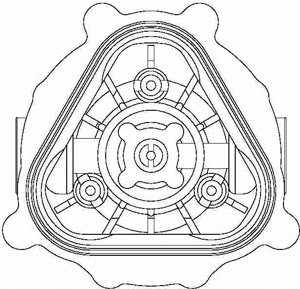
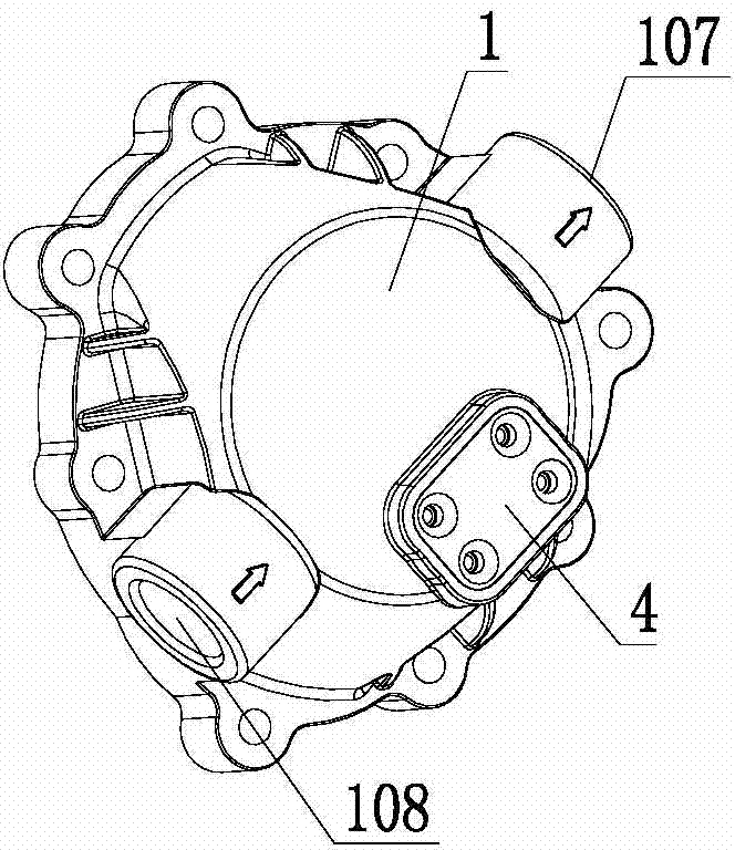
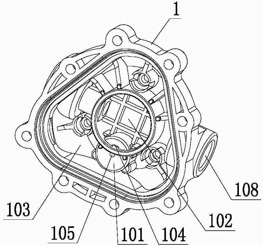
[0013] Such as Figure 2-4 As shown, a bias pressure relief device of a diaphragm pump, the pump cover 1 constituting the diaphragm pump is divided into a high-pressure chamber 102 and a low-pressure chamber 103 by a collector plate. The high-pressure chamber 102 is located in the center of the pump cover 1 and communicates with the water outlet hole 107 of the diaphragm pump. The low-pressure chamber 103 is located at the periphery of the high-pressure chamber 102 and communicates with the water inlet 108 of the diaphragm pump. The pressure relief device is arranged on the pump cover body 1, and includes an inwardly recessed chamber 101 formed on the pump cover body 1; a high-altitude hole 104 and a high-altitude hole 104 which are respectively connected to the high-pressure chamber 102 and the low-pressure chamber 103 of the diaphragm pump in the chamber 101. The low-pressure hole 105; the piston 2, the spring 3 and the cover 4 installed in the chamber 101 in sequence. The...


PUM


Abstract

The invention discloses an offset type pressure relief device of a membrane pump. The offset type pressure relief device is arranged on a pump cover body and comprises a chamber, a high-pressure hole, a low-pressure hole, a piston, a spring and a sealing cover, wherein the chamber is formed in the pump cover body and is inwards concave; the high-pressure hole and the low-pressure hole which are respectively communicated with a high-pressure cavity and a low-pressure cavity of the membrane pump are formed in the chamber; the piston, the spring and the sealing cover are sequentially arranged in the chamber; the chamber is arranged at one side which is inclined to the pump cover body, the high-pressure hole and the low-pressure hole are both formed in the bottom part of the chamber, and the high-pressure hole and the low-pressure hole are blocked by the end parts of the piston. Since the offset type pressure relief device disclosed by the invention is adopted, the fluid flowing resistance is reduced, the efficiency of the membrane pump is increased, the noise of the membrane pump is reduced, and fluid cannot flow into the pressure relief chamber to soak the spring; since the offset type pressure relief device is simple in structure, a die is simplified, the cost of the die is reduced, and the cost of an injection molding material is reduced.

Description

technical field [0001] The invention relates to the technical field of diaphragm pumps, in particular to an electric diaphragm pump applied to water dispensers. Background technique [0002] At present, electric diaphragm pumps are installed on some water dispensers to realize electric water pumping. The diaphragm pump converts the rotational motion of the motor into the periodic reciprocating motion of the balance wheel through the eccentric bearing. The one-way valve opens and closes alternately, so that water is continuously sucked in and discharged. The pump cover that constitutes the diaphragm pump is divided into a high-pressure chamber and a low-pressure chamber by a collector plate. The high-pressure chamber is located in the center of the pump cover and communicates with the outlet hole of the diaphragm pump. The low-pressure chamber is located on the periphery of the high-pressure chamber and communicates with the water inlet hole of the diaphragm pump. [0003...

Claims


Application Information

Patent Timeline
IPC IPC(8): F04B53/10
Inventor 曾宪雄
Owner 曾宪雄
Why Eureka
Try Eureka