
In-line fuse capable of achieving safety on-line detection

An in-line and safe technology, applied in fuzes, weapon accessories, offensive equipment, etc., can solve problems that are difficult to eliminate, difficult to disassemble, and damaged, and achieve the effects of convenient manual disassembly, avoiding mutual interference, and improving assembly efficiency

Pending Publication Date: 2020-02-21
ARMY ENG UNIV OF PLA
View PDF0 Cites 0 Cited by
  • Summary
  • Abstract
  • Description
  • Claims
  • Application Information

AI Technical Summary

Problems solved by technology

[0004] 1. In the prior art, the detection work of the in-line fuze is still in the pre-detection stage. After the bombing is completed, the operating conditions for changing the simulated detonator are generally not available, that is, it is difficult to carry out online testing. If a fault occurs, it will be difficult to eliminate, thus create greater safety hazards;
[0005] 2. The main components of the general in-line fuze adopt a fixed installation structure. After the assembly is completed, it is difficult to disassemble it in the later stage, and it is not convenient to troubleshoot the fault point in time and carry out maintenance and replacement;
[0006] 3. The general in-line fuze lacks corresponding strengthening and improvement in the shell part, and the protection effect is relatively weak. It may be subject to external collisions and vibrations, which may cause the interface to fall off or be damaged, and then cause corresponding failures

Method used


Image

  • In-line fuse capable of achieving safety on-line detection
  • In-line fuse capable of achieving safety on-line detection
  • In-line fuse capable of achieving safety on-line detection

Examples


Embodiment Construction

[0028] The following will clearly and completely describe the technical solutions in the embodiments of the present invention with reference to the accompanying drawings in the embodiments of the present invention. Obviously, the described embodiments are only some, not all, embodiments of the present invention. Based on the embodiments of the present invention, all other embodiments obtained by persons of ordinary skill in the art without making creative efforts belong to the protection scope of the present invention.

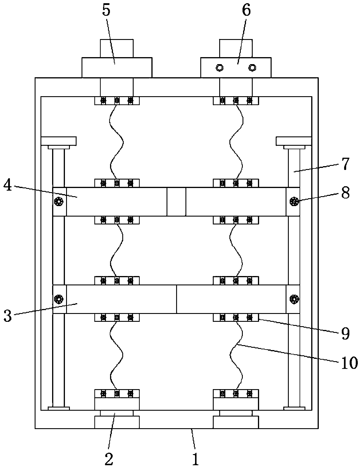
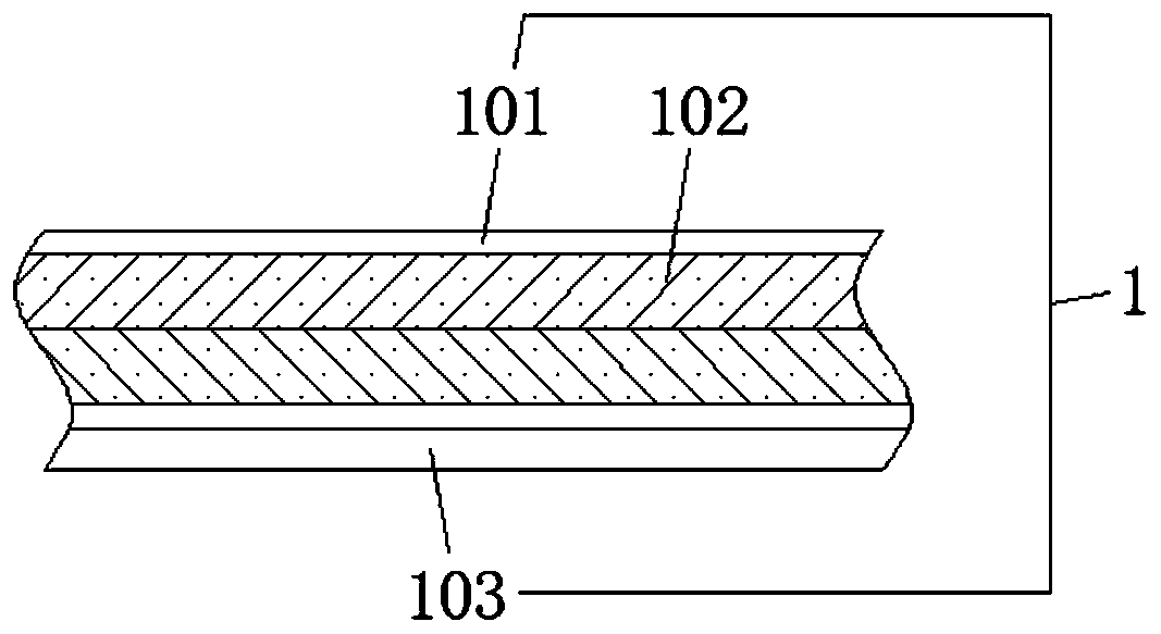
[0029] see Figure 1-4 , the present invention provides a technical solution: an in-line fuze capable of safe on-line detection, including a housing 1, a detonator module 2, a high-voltage detonation module 3, a control circuit module 4, an electrical interface 5 and a test interface 6, and the housing 1 The detonator module 2 is installed on the left and right sides of the bottom, and the left and right sides of the top of the housing 1 are respectively equip...


PUM


Abstract

The invention discloses an in-line fuse capable of achieving safety on-line detection. The in-line fuse comprises a shell, detonator modules, a high-voltage initiation module, a control circuit module, an electrical interface and a testing interface, wherein the detonator modules are installed on the left side and the right side of the bottom of the shell respectively, and the electrical interfaceand the testing interface are inserted on the left side and the right side of the top of the shell respectively; the left side and the right side of the interior of the shell are each provided with astand column, a high-voltage initiation module and a control circuit module are sequentially arranged between the stand columns from bottom to top, and the left end and the right end of the high-voltage initiation module and the left end and the right end of the control circuit module are both connected with the stand columns through positioning mechanisms; and one end of each detonator module, one end of the high-voltage initiation module, one end of the control circuit module, one end of the electrical interface and one end of the testing interface are each provided with a wiring mechanism.According to the in-line fuse capable of achieving safety on-line detection, on-line high-efficiency detection of the in-line fuses is realized, the assembly efficiency of the in-line fuses is improved, and the safety during use of the in-line fuses is improved.

Description

technical field [0001] The invention relates to the technical field of in-line fuzes, in particular to an in-line fuze capable of safe on-line detection. Background technique [0002] In-line fuze, that is, a fuze system without explosion-proof explosion sequence composed of electronic safety and disarming device and shock plate detonator based on insensitive charge. Compared with traditional mechanical and electromechanical fuzes, it has higher safety, reliability and testability. Before production and loading, the shock-disc detonator can be replaced with a dummy detonator, and its fuze performance can be fully tested. [0003] However, there are still certain problems in the existing in-line fuze, and the specific problems have the following points: [0004] 1. In the prior art, the detection work of the in-line fuze is still in the pre-detection stage. After the bombing is completed, the operating conditions for changing the simulated detonator are generally not availa...

Claims


Application Information

Patent Timeline
Patent Type & Authority Applications(China)
IPC IPC(8): F42C15/40F42C21/00
CPCF42C15/40F42C21/00
Inventor 李超旺周晓东吕静崔亮王毅方丹张晓良关鹏鹏
Owner ARMY ENG UNIV OF PLA
Learn More