F-P cavity type high-temperature large-strain optical fiber sensor

An optical fiber sensor, F-P technology, applied in the field of sensors, can solve problems such as low measurement accuracy, range influence, and low precision, and achieve the effects of avoiding range limitation, reducing transmission resistance, and improving accuracy

Pending Publication Date: 2020-02-21
DALIAN UNIV OF TECH
View PDF0 Cites 5 Cited by
  • Summary
  • Abstract
  • Description
  • Claims
  • Application Information

AI Technical Summary

Problems solved by technology

This type of optical fiber sensor is limited by the ultimate strain of the optical fiber, and its measurement range is small, so it cannot accurately measure the strain of the substrate with large deformation
Most high-temperature strain sensors, high-temperature-resistant pressure sensors and other optical fiber sensors are only for single-parameter measurement, and there are relatively few technical researches on temperature and strain dual-parameter measurement, and there are problems such as low measurement accuracy and low reliability.
[0004] To sum up, the current high-temperature strain sensors based on optical fibers have problems such as complex structure, low precision, and low reliability.
Most fiber optic sensors are affected by the measuring range and encounter difficulties in measuring the strain of large deformation substrates

Method used


Image

  • F-P cavity type high-temperature large-strain optical fiber sensor
  • F-P cavity type high-temperature large-strain optical fiber sensor
  • F-P cavity type high-temperature large-strain optical fiber sensor

Examples


Embodiment 1

[0031] Embodiment 1: High-temperature strain sensor using Fabry-Perot (F-P) interference when using the end face of an optical fiber as a mirror

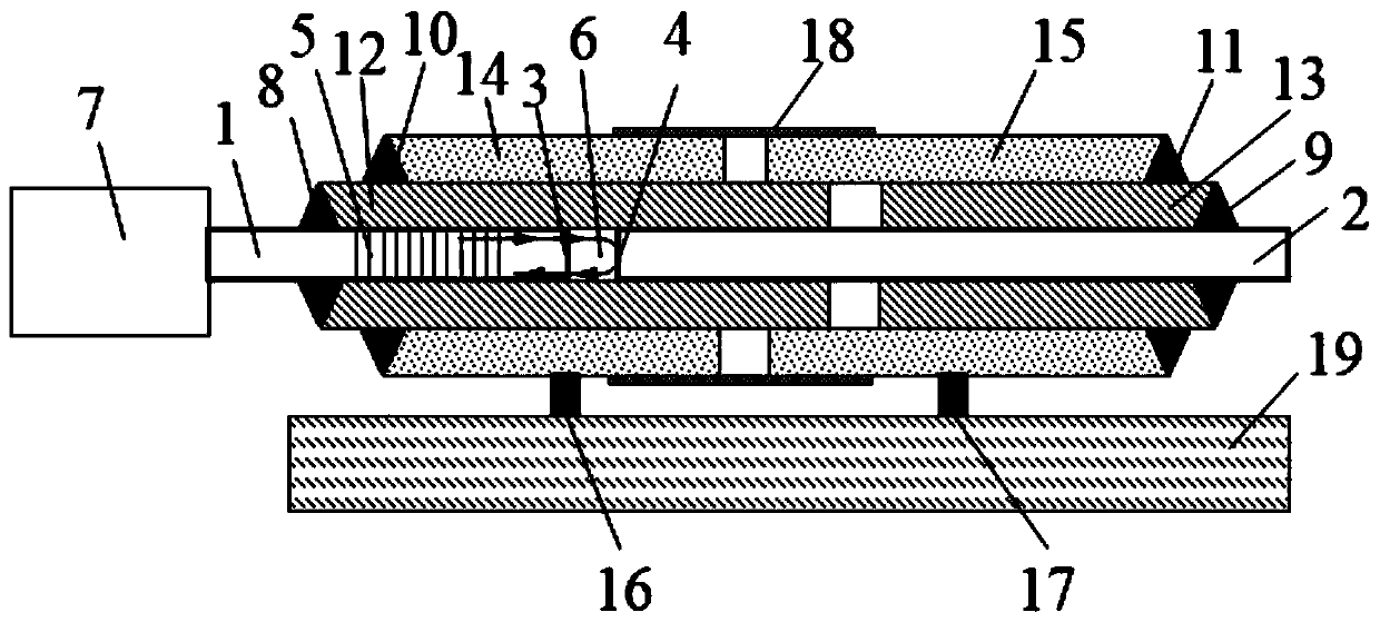
[0032] An F-P cavity-type high-temperature and large-strain optical fiber sensor, including a transmission optical fiber 1, an optical fiber 2, an inner sleeve, an outer sleeve, a clamp, a connecting key, and a sealing structure 18;

[0033] One end of the transmission fiber 1 is connected to the spectrometer 7, and the other end is used as the first reflective surface 3 and the end is opposite to the optical fiber 2 as the second reflective surface 4, and the cavity between the two is a Fabry-Perot interference cavity 6. A temperature sensor 5 is written on the transmission optical fiber 1, and the temperature sensor 5 is located in the first inner casing 12;

[0034] The inner sleeve includes a first inner sleeve 12 and a second inner sleeve 13, both of which are sleeved on the outside of the transmission optical fiber 1 and the o...

Embodiment 2

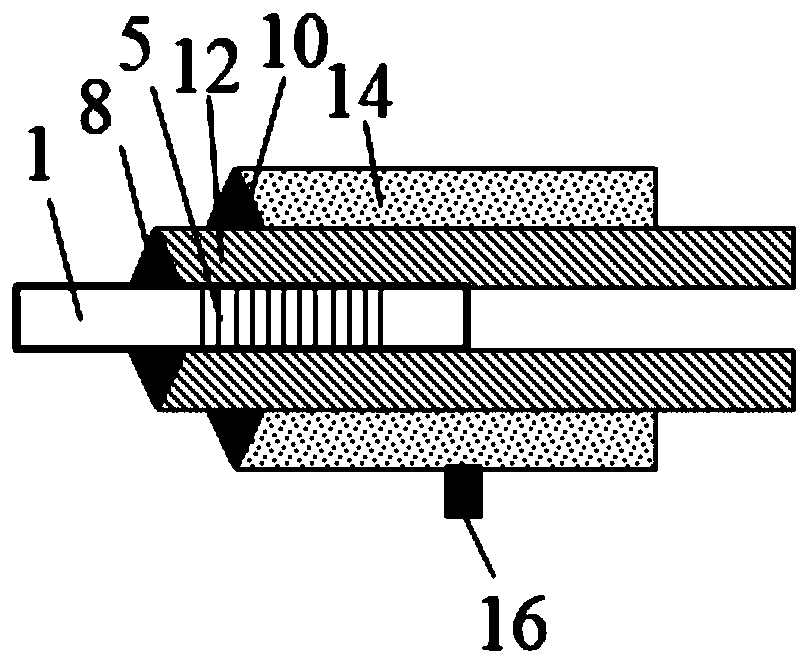
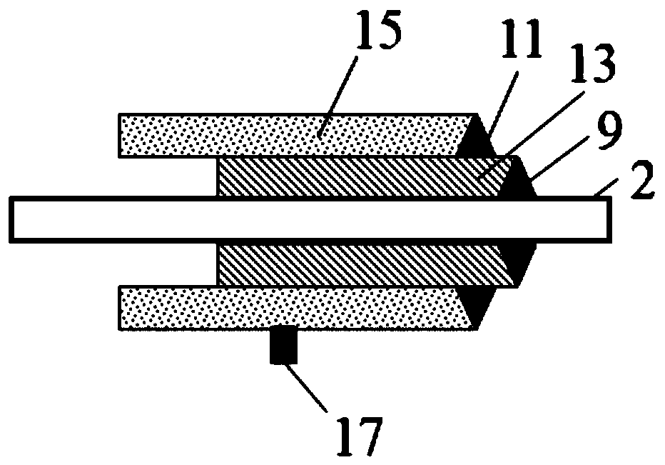
[0043] Embodiment 2: When a reflecting mirror is pasted, the F-P cavity type high-temperature and large-strain optical fiber sensor is a high-temperature strain sensor of Fabry-Perot (F-P) interference, and the high-temperature strain sensor includes a transmission optical fiber 1, a plane mirror 20, The first reflective surface 3 , the second reflective surface 4 , the first inner sleeve 12 , the first outer sleeve 14 , the second outer sleeve 15 , the first clamp 16 , the second clamp 17 and the sealing structure 18 . The material of each part is the same as that in Embodiment 1 when the end surface of the optical fiber 2 is used as the reflection surface.

[0044] As shown in Figure 2, when the second reflective surface 4 is a plane mirror instead of an optical fiber, only the first inner sleeve 12, the first outer sleeve 14 and the second outer sleeve 15 are needed, and the second inner sleeve is not needed 13. The transmission optical fiber 1 is inserted from the first in...


PUM


Abstract

The invention belongs to the technical field of sensors, and discloses an F-P cavity type high-temperature large-strain optical fiber sensor, which comprises a transmission optical fiber, a reflectingmirror, an inner sleeve, an outer sleeve, a clamp for fixing the outer sleeve and a sealing structure; the transmission optical fiber can ensure the coaxiality through mutual embedding of the two sets of sleeve devices, and a Fabry-Perot cavity, namely an F-P cavity, is formed between the end face of the optical fiber and the reflecting mirror. The cavity length of the F-P cavity can be changed due to deformation of a measured material, so that the change of a reflection spectrum is caused, and the strain of the material is monitored by analyzing the variation of the spectrum. The F-P cavitytype high-temperature large-strain optical fiber sensor is based on a high-temperature strain gauge of a Fabry-Perot interference principle, and can measure material deformation of tens of thousands to hundreds of thousands of micro-strain levels at high temperature. The optical fiber sensor can realize measurement of large strain at high temperature and simultaneous measurement of temperature andstrain parameters, and is high in measurement precision, high in stability and easy to popularize.

Description

technical field [0001] The invention belongs to the technical field of sensors, in particular to an F-P cavity type high-temperature and large-strain optical fiber sensor. Background technique [0002] As the application range of optical fiber continues to expand, people's requirements for its measurement performance are also getting higher and higher. In actual engineering, we sometimes need fiber optic sensors to achieve strain measurement at high temperatures. For example, in the aerospace field, aircraft must withstand high temperature, high pressure, corrosion and other harsh operating environments. How to use strain sensors to detect the stress of aircraft structures in high temperature environments Change is an urgent problem to be solved. Due to the influence of high temperature environment, optical fiber cannot accurately measure material strain, which greatly reduces the reliability of optical fiber strain sensor. In order to solve this problem, scholars at home ...

Claims


Application Information

Patent Timeline
Patent Type & Authority Applications(China)
IPC IPC(8): G01B11/16
CPCG01B11/161
Inventor 唐福建赵丽芝李宏男
Owner DALIAN UNIV OF TECH
Why Eureka
Try Eureka