
Protection device for sensor

A protection device and sensor technology, which is applied in the field of rail transit, can solve the problems of affecting the sensing performance of the sensor, damaging the sensor, etc.

Pending Publication Date: 2020-02-21
CRSC RESEARCH & DESIGN INSTITUTE GROUP CO LTD
View PDF0 Cites 0 Cited by
  • Summary
  • Abstract
  • Description
  • Claims
  • Application Information

AI Technical Summary

Problems solved by technology

[0002] In order to avoid damage to the sensor or affect the sensing performance of the sensor due to changes in external conditions, it is very necessary to install a sensor protection device outside the sensor. The design of the fiber grating sensor protection device needs to consider maintaining the integrity of the rail, 15 years of service life, engineering Implementation feasibility, easy maintenance, convenient transportation and other issues, but the current fiber grating sensor protection device is difficult to solve the above technical problems

Method used


Image

  • Protection device for sensor
  • Protection device for sensor
  • Protection device for sensor

Examples


no. 1 approach

[0045] First embodiment: the optical cable can record m groups of fiber grating sensors, each group of sensors contains n fiber grating sensors, and each group of sensors is distributed from near to far in space; the FBG sensors of each group are distributed in the same optical fiber , the FBG sensors in each group are connected in series, and the working wavelengths of the FBG sensors in each group are different; image 3 and Figure 4 As shown, Group 1 FBG sensors include FBG 1-1 、FBG 1-2 ...FBG 1-n , Group 2 FBG sensors include FBG 2-1 、FBG 2-2 ...FBG 2-n , and so on, the mth group of FBG sensors includes FBG m-1 、FBG m-2 ...FBG m-n ; The working wavelength of each FBG sensor in the first group is different, and the wavelength of each FBG sensor in the first group is λ 1 , lambda 2 ... λ n ; The working wavelength of each FBG sensor in the second group is different, and the wavelength of each FBG sensor in the second group is λ 1 , lambda 2 ... λ n ; By analog...

no. 2 approach

[0046] Second embodiment: the optical cable can record n ​​groups of fiber grating sensors, each group of sensors contains m fiber grating sensors, and each group of sensors is distributed from near to far in space; the FBG sensors in each group are distributed on different optical fibers In , the working wavelength of each FBG sensor in each group is the same. Such as Figure 5 and Figure 6 As shown, Group 1 FBG sensors include FBG 1-1、FBG 2-1 ...FBG m-1 , Group 2 FBG sensors include FBG 1-2 、FBG 2-2 ...FBG m-2 , and so on, the nth group of FBG sensors includes FBG 1-n 、FBG 2-n ...FBG m-n ; The working wavelength of each FBG sensor in the first group is the same, and the wavelength of each FBG sensor in the first group is λ 1 ; The working wavelength of each FBG sensor in the second group is the same, and the wavelength of each FBG sensor in the second group is λ 2 ; By analogy, the working wavelength of each FBG sensor in the nth group is the same, and the wavele...


PUM


Abstract

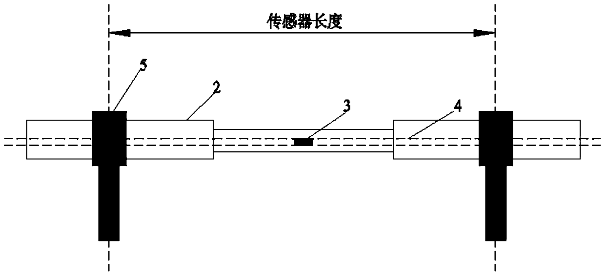
The invention belongs to the technical field of rail transit, and particularly relates to a protection device for a sensor. The protection device comprises a sheath, wherein the sheath is formed by sequentially connecting a plurality of soft sheaths and hard sheaths; and the sensor is a fiber grating sensor. The protection device disclosed by the invention is convenient to assemble, convenient totransport and install and convenient to disassemble and replace the sensor when a certain section of sensor fails, and is suitable for large-scale production and application. In addition, the protection device can be used for point track occupancy inspection and can also be used for continuous track occupancy inspection. When the protection device is used for the continuous track occupancy inspection, train length measurement, speed measurement, train integrity checking and the like can be synchronously realized.

Description

technical field [0001] The invention belongs to the technical field of rail transit, and in particular relates to a sensor protection device. Background technique [0002] In order to avoid damage to the sensor or affect the sensing performance of the sensor due to changes in external conditions, it is very necessary to install a sensor protection device outside the sensor. The design of the fiber grating sensor protection device needs to consider maintaining the integrity of the rail, 15 years of service life, engineering Implementation feasibility, easy maintenance, convenient transportation and other issues, but the current fiber grating sensor protection device is difficult to solve the above technical problems. [0003] Therefore, there is an urgent need to develop a sensor protection device that can solve the above technical problems. Contents of the invention [0004] In order to improve the above technical problems, the present invention provides a protective devi...

Claims


Application Information

Patent Timeline
IPC IPC(8): G01D5/353G01D11/24
CPCG01D5/35316G01D11/24
Inventor 潘继军靖焱林赵泽冯皓闻瑞杨明张劼梁斌
Owner CRSC RESEARCH & DESIGN INSTITUTE GROUP CO LTD
Learn More