Novel impeller electromagnetic flowmeter

An electromagnetic flowmeter and impeller technology, which is applied in the application of electromagnetic flowmeters to detect fluid flow, volume/mass flow generated by electromagnetic effects, etc. Different types of instruments are used together to achieve the effects of fast measurement speed, compact structure, low installation, commissioning and maintenance costs

Active Publication Date: 2020-02-21
CHONGQING UNIV
View PDF8 Cites 2 Cited by
  • Summary
  • Abstract
  • Description
  • Claims
  • Application Information

AI Technical Summary

Problems solved by technology

[0005] The application of electromagnetic flowmeter has certain limitations. It can only measure the liquid flow of conductive medium, and cannot measure the flow of non-conductive medium.
The installation and commissioning of electromagnetic flowmeters are more complicated than other flowmeters, and the requirements are stricter
The transmitter and converter must be used together, and two different types of instruments cannot be used between the two

Method used


Image

  • Novel impeller electromagnetic flowmeter
  • Novel impeller electromagnetic flowmeter
  • Novel impeller electromagnetic flowmeter

Examples


Embodiment 1

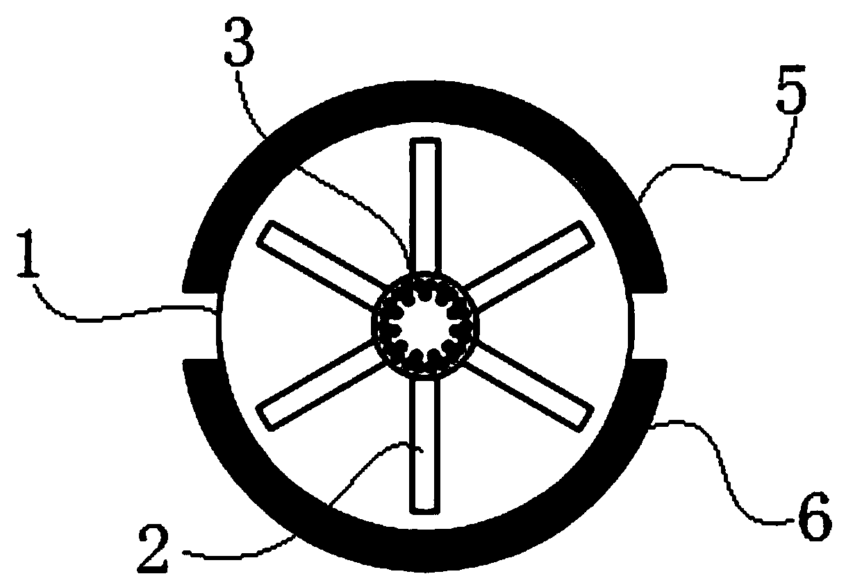
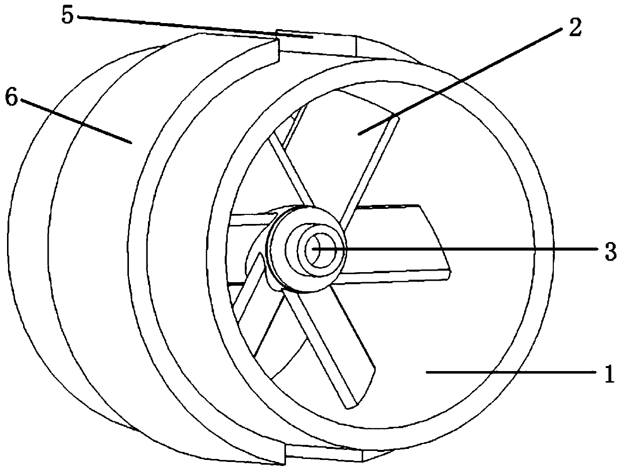
[0043] This embodiment discloses a novel impeller electromagnetic flowmeter, see figure 1 , figure 2 with Picture 9 , Including pipeline 1, impeller 2, coil 3, support frame 4, magnet assembly and electrical measuring instruments.

[0044] See Picture 10 The supporting frame 4 includes a housing 401 and three supporting parts 402.

[0045] In this embodiment, the housing 401 is cylindrical, one end of which is closed and the other end is open. The three supporting parts 402 are evenly distributed on the outer wall of the housing 401. The supporting frame 4 is located in the pipe 1, the axis of the housing 401 coincides with the axis of the pipe 1, and the three supporting parts 402 are all fixed on the inner wall of the pipe 1.

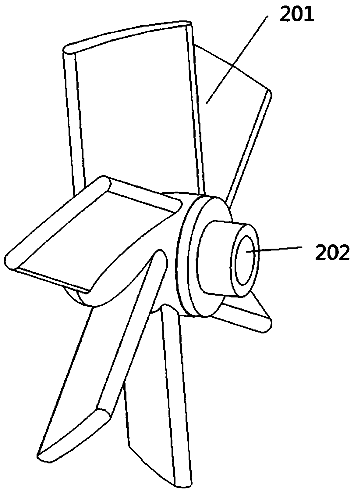
[0046] See image 3 , Image 6 with Figure 7 The impeller 2 includes a wheel body 201 and six blades 202.

[0047] The wheel body 201 is a hollow structure with one end closed and the other end open. The six blades 202 are evenly distributed on the out...

Embodiment 2

[0054] This embodiment provides a relatively basic implementation, a new type of impeller electromagnetic flowmeter, see figure 1 , figure 2 with Picture 9 , Including pipeline 1, impeller 2, coil 3, support frame 4, magnet assembly and electrical measuring instruments.

[0055] See Picture 10 The supporting frame 4 includes a housing 401 and three supporting parts 402.

[0056] In this embodiment, the housing 401 is cylindrical, one end of which is closed and the other end is open. The three supporting parts 402 are evenly distributed on the outer wall of the housing 401. The supporting frame 4 is located in the pipe 1, the axis of the housing 401 coincides with the axis of the pipe 1, and the three supporting parts 402 are all fixed on the inner wall of the pipe 1.

[0057] See image 3 , Image 6 with Figure 7 The impeller 2 includes a wheel body 201 and six blades 202.

[0058] The wheel body 201 is a hollow structure with one end closed and the other end open. The six blad...

Embodiment 3

[0065] The main structure of this embodiment is the same as that of Embodiment 2. Furthermore, a dynamic sealing device 7 is provided between the open end of the wheel body 201 and the open end of the housing 401.


PUM


Abstract

The invention discloses a novel impeller electromagnetic flowmeter. The novel impeller electromagnetic flowmeter comprises a pipeline, an impeller, a coil, a supporting frame, a magnet assembly and anelectrical measuring instrument; the supporting frame comprises a shell and at least one support part; the support parts are connected to the outer wall of the shell; the supporting frame is locatedin the pipeline, and the support parts of the supporting frame are connected with the inner wall of the pipeline; the impeller comprises an impeller body and a plurality of blades; the blades are evenly distributed on the outer wall of the impeller body; the opening end of the impeller body is rotatably connected into the opening end of the shell; the coil is installed in the impeller body, a wireof the coil penetrates into the shell; the magnet assembly comprises a magnet I and a magnet II; the magnet I and the magnet II are symmetrically arranged on the outer wall of the pipeline; and the coil is located between the magnet I and the magnet II; the electric measuring instrument is electrically connected with the coil, and the electric measuring instrument measures the induced electromotive force frequency of the coil. The ovel impeller electromagnetic flowmeter is compact in structure, low in installation and debugging and maintenance costs, does not require too detailed operation compared with other flowmeters and is excellent in calibration performance.

Description

Technical field [0001] The invention belongs to the field of fluid measurement, and specifically relates to a novel impeller electromagnetic flowmeter. Background technique [0002] At present, in all fields of chemical industry, energy, water conservancy, etc., the measurement and control of fluids are very important. For this reason, many fluid measurement devices have been born. Today, when the process requirements are becoming more and more stringent, it is necessary to master the relevant pipeline flow parameters to operate the equipment. , Scientific experiments, and system maintenance are very important. [0003] The existing measuring flow meters mainly include electromagnetic flow meters, ultrasonic flow meters, vortex flow meters, orifice flow meters, elbow flow meters and so on. However, as a whole, these measuring devices have high accuracy and high cost, low-cost operations are complicated, and simple operations have insufficient accuracy. [0004] See Figure 13 , For ...

Claims


Application Information

Patent Timeline
Patent Type & Authority Applications(China)
IPC IPC(8): G01F1/58
CPCG01F1/58
Inventor 步珊珊祁伟周文雄
Owner CHONGQING UNIV
Why Eureka
Try Eureka