Unlock instant, AI-driven research and patent intelligence for your innovation.
A wing simulation test bench driven by linear motor
What is Al technical title?
Al technical title is built by PatSnap Al team. It summarizes the technical point description of the patent document.
A linear motor and wing simulation technology, applied in aerodynamic testing, machine/structural component testing, aircraft component testing, etc., can solve problems such as the lack of aerodynamic theoretical guidance for the wing system, and achieve good applicability Effect
Active Publication Date: 2021-03-26
UNIV OF SHANGHAI FOR SCI & TECH
View PDF12 Cites 0 Cited by
Summary
Abstract
Description
Claims
Application Information
AI Technical Summary
This helps you quickly interpret patents by identifying the three key elements:
Problems solved by technology
Method used
Benefits of technology
Problems solved by technology
[0002] Flapping-wing aircraft has many advantages that traditional fixed-wing aircraft do not have. However, due to the lack of aerodynamic theoretical guidance for its core component wing system, it is necessary to use a wing simulation test bench for a large number of experiments when designing a flapping-wing aircraft. However, the existing wing simulation test bench cannot perform force analysis experiments on the wings of flapping aircraft with different wing types and different flapping laws.
Method used
Image
Click on the blue label to locate the original text in one second.
Reading with bidirectional positioning of images and text.
Examples
Embodiment Construction
[0020] In order to make the technical means and effects realized by the present invention easy to understand, the present invention will be described in detail below in conjunction with the embodiments and accompanying drawings.
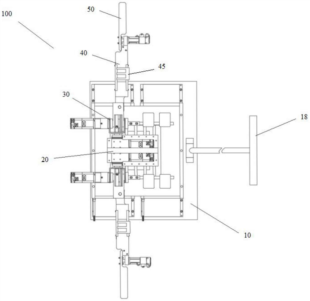
[0021] figure 1 It is a top view of the device of the linear motor-driven wing simulation test bench in the embodiment of the present invention.
[0022] Such as figure 1 As shown, the wing simulation test bench 100 driven by a linear motor in this embodiment has a bottom assembly 10 , a fuselage assembly 20 , a chest assembly 30 , a first wing assembly 40 and a second wing assembly 50 .
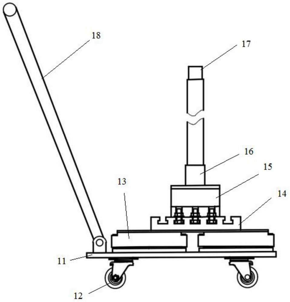
[0023] figure 2 It is a structural schematic diagram of the bottom assembly in the embodiment of the present invention.
[0024] Such as figure 2 As shown, the bottom assembly 10 has a base 11, four wheels 12 arranged under the base 11, two linear motors 13 arranged on the base 11, T-shaped slots 14 arranged on the linear motors 13, fixed on the T-shaped slot...
PUM
Abstract
The invention provides a wing simulation test bench driven by a linear motor. The test bench comprises a bottom assembly which is provided with a pedestal, wheels, linear motors, T-shaped grooves, a six-axis force measurement sensor, a bottom supporting disc, a long connecting rod, and a push rod, a machine body assembly which is provided with a machine body mounting plate, a bottom flange plate,a first servo motor, a first speed reducer, a bearing mounting plate and a bearing cover, the two chest assemblies which are symmetrically arranged on two sides of the machine body assembly and comprise center connecting plates, stepped flange plates, auxiliary supporting flange plates, air bag supporting rods, auxiliary supporting air bags, second speed reducers, second servo motors, concave connecting plates and torque sensors, two first wing assemblies which are connected with the two chest assemblies and comprise first wing bodies, guide grooves, guide plates, clamping jaws, motor mountingblocks and third servo motors, and the two second fin assemblies which are connected with the two first fin assemblies correspondingly and comprise second fin bodies and second fin flanges.
Description
technical field [0001] The invention relates to a wing simulation test bench, in particular to a wing simulation test bench driven by a linear motor. Background technique [0002] Flapping-wing aircraft has many advantages that traditional fixed-wing aircraft do not have. However, due to the lack of aerodynamic theoretical guidance for its core component wing system, it is necessary to use a wing simulation test bench for a large number of experiments when designing a flapping-wing aircraft. Experiment and practice, and the existing wing simulation test bench can't carry out stress analysis experiment to the wing of the flapping wing aircraft of different wing types, different flapping rules preferably. Contents of the invention [0003] The present invention is carried out in order to solve the above problems, and the purpose is to provide a wing simulation test bench driven by a linear motor. [0004] The invention provides a wing simulation test bench driven by a linea...
Claims
Application Information
Patent Timeline
Application Date:The date an application was filed.
Publication Date:The date a patent or application was officially published.
First Publication Date:The earliest publication date of a patent with the same application number.
Issue Date:Publication date of the patent grant document.
PCT Entry Date:The Entry date of PCT National Phase.
Estimated Expiry Date:The statutory expiry date of a patent right according to the Patent Law, and it is the longest term of protection that the patent right can achieve without the termination of the patent right due to other reasons(Term extension factor has been taken into account ).
Invalid Date:Actual expiry date is based on effective date or publication date of legal transaction data of invalid patent.

