In-place needle for detecting attachment of device

A technology for detectors and devices, which is applied to the components of electrical measuring instruments, measuring devices, instruments, etc., can solve problems such as test failures, device mounting irregularities, and probe deviations, and achieve convenient installation and low cost , small size effect

Inactive Publication Date: 2020-02-21
深圳市明信测试设备股份有限公司
View PDF5 Cites 0 Cited by
  • Summary
  • Abstract
  • Description
  • Claims
  • Application Information

AI Technical Summary

Problems solved by technology

[0004] 1. There are defects in the function, and the irregularity of device mounting often causes the probe to be misaligned, resulting in test failure

Method used


Image

  • In-place needle for detecting attachment of device
  • In-place needle for detecting attachment of device

Examples


Embodiment Construction

[0023] In order to make the object, technical solution and advantages of the present invention clearer, the present invention will be further described in detail below in conjunction with the accompanying drawings and embodiments. It should be understood that the specific embodiments described here are only used to explain the present invention, not to limit the present invention.

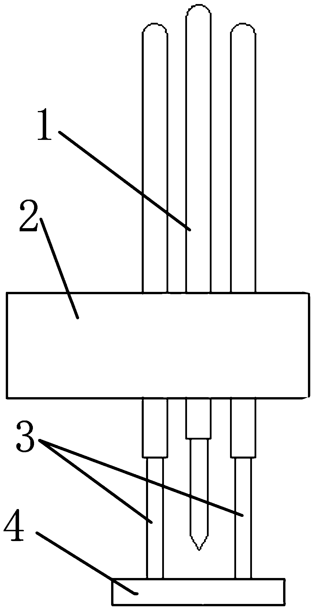
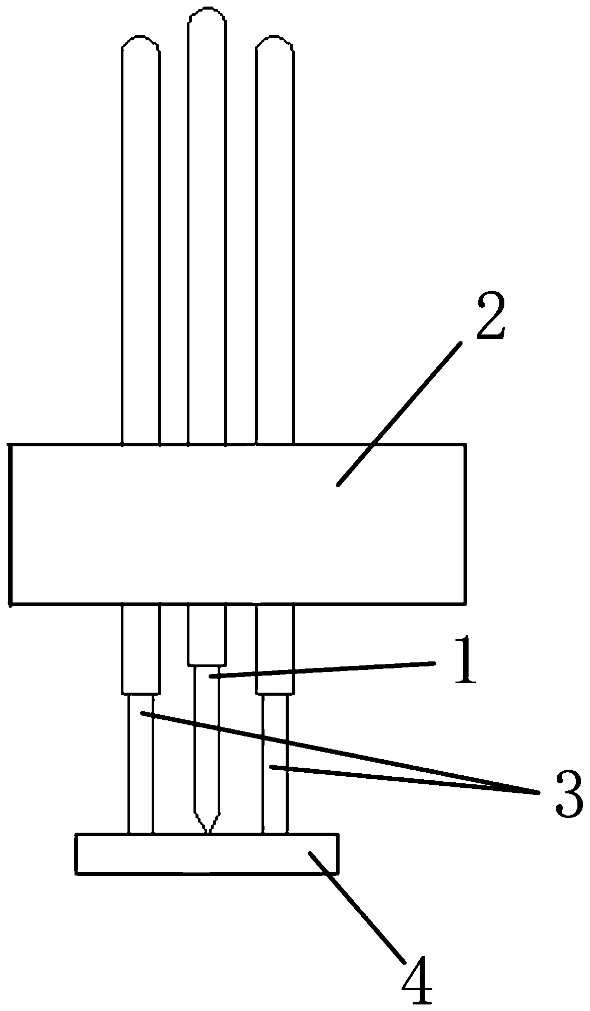
[0024] Such as figure 1 As shown, an in-position pin for detecting device mounting includes: a middle thimble 1, a probe mounting block 2, an elastic thimble 3 and a copper sheet 4;

[0025] The elastic thimble 3 is installed on the probe mounting block 2, and the middle thimble 1 is installed on the probe mounting block 2 and placed in the gap between the elastic thimbles 3. The elastic thimble 3 is longer than the middle thimble 1 under no pressure, and the elastic The top of the thimble 3 is fixedly connected with the copper sheet 4, and there is a movable gap between the middle thimble 1 and t...


PUM


Abstract

The invention relates to an in-place needle for detecting attachment of a device, which comprises a middle ejector needle, a probe installation block, elastic ejector needles and a cooper sheet, wherein the two elastic ejector needles are installed on the probe installation block, the middle ejector needle is installed on the probe installation block and is arranged in a gap between the elastic ejector needles, the elastic ejector needles are longer than the middle ejector needle in a non-pressure state, telescopic ends of the elastic ejector needles are fixedly connected with the copper sheet, a movable gap is formed between the middle ejector needle and the copper sheet, when the copper sheet touches an element to be detected on a PCBA (Printed Circuit Board Assembly) board, the elasticejector needles are compressed, the copper sheet touches the top of the middle ejector needle, and at the moment, the copper sheet is in current conduction with the middle ejector needle, so as to judge whether the element on the PCBA board is attached. The in-place needle of the invention has the beneficial effects that: the device on the PCBA board is contacted through a plane, a test effect isnot influenced by irregular device attachment, and a structure is simple.

Description

technical field [0001] The invention relates to the field of detection of electronic components, and more specifically relates to an in-position pin for detecting device mounting. Background technique [0002] Today, with the development of the electronics industry, electronic circuit components have used small mount components and small ball diameter BGA devices on a large scale. Due to their particularity, the number of samples for sampling inspection at the factory will not exceed 0.1% (5,000-10,000 per reel, all components are scrapped after sampling), the overall proportion confidence is 90%, the risk of the user is usually set at 10%, there will be a risk of missed inspection for the defects of components, and the traditional The test method is to judge whether the components on the PCBA board are mounted by using the low pin and the high pin to conduct after the probe is compressed. Due to the irregularity of the device mounting, the probe is often misplaced and the t...

Claims


Application Information

Patent Timeline
IPC IPC(8): G01R1/067G01R31/28
CPCG01R1/06716G01R1/06794G01R31/2808
Inventor 吴少华邓锦辉胡志光
Owner 深圳市明信测试设备股份有限公司
Why Eureka
Try Eureka