Automatic wiring robot for power distribution cabinet

A technology of automatic wiring and robots, applied in the direction of line/collector components, circuits, connections, etc., can solve the problems of low intelligence, low efficiency of wiring of power distribution cabinets, and affecting the efficiency of wiring of power distribution cabinets, etc., to achieve intelligent High degree of automation, high wiring efficiency, and the effect of promoting production

Inactive Publication Date: 2020-02-21
九江清研神盾科技有限公司
View PDF0 Cites 4 Cited by
  • Summary
  • Abstract
  • Description
  • Claims
  • Application Information

AI Technical Summary

Problems solved by technology

The common wiring methods of power distribution cabinets are generally manual, which makes the wiring efficiency of power distribution cabinets low and the error is large, which does not meet the actual production and use needs of power distribution cabinets, and manual wiring is greatly affected by human factors. The production quality of the power distribution cabinet cannot be effectively guaranteed, thereby affecting the subsequent use of the power distribution cabinet; at the same time, the existing wiring devices of the power distribution cabinet are relatively low in intelligence and cannot meet the wiring requirements of different positions of the power distribution cabinet, making the power distribution cabinet The wiring processing steps are complicated, which seriously affects the efficiency of the wiring of the power distribution cabinet, thereby affecting the actual production of the power distribution cabinet

Method used


Image

  • Automatic wiring robot for power distribution cabinet
  • Automatic wiring robot for power distribution cabinet
  • Automatic wiring robot for power distribution cabinet

Examples


Embodiment Construction

[0026] The following will clearly and completely describe the technical solutions in the embodiments of the present invention with reference to the accompanying drawings in the embodiments of the present invention. Obviously, the described embodiments are only some, not all, embodiments of the present invention. Based on the embodiments of the present invention, all other embodiments obtained by persons of ordinary skill in the art without creative efforts fall within the protection scope of the present invention.

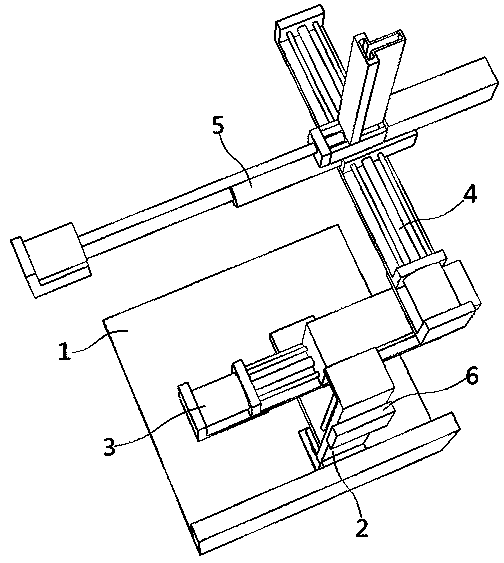
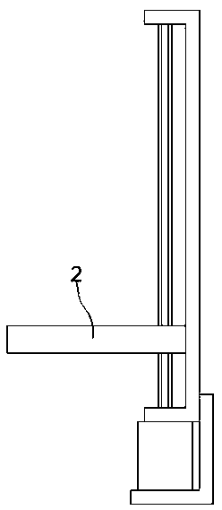
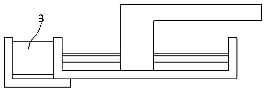
[0027] see Figure 1-9 As shown, the present invention is an automatic wiring robot for power distribution cabinets, including a base 1, a first moving mechanism 2 is fixed on one surface of the base 1, a second moving mechanism 3 is fixed on the first moving mechanism 2, and the second moving mechanism 3 The third mobile mechanism 4 is fixed on the third mobile mechanism 4, and the wiring mechanism 5 is fixed on the third mobile mechanism 4. The third mobile mecha...


PUM


Abstract

The invention discloses an automatic wiring robot for a power distribution cabinet, and relates to the technical field of power distribution cabinet wiring. The robot comprises a base. A first movingmechanism is fixed on one surface of the base. A second moving mechanism is fixed on the first moving mechanism. A third moving mechanism is fixed on the second moving mechanism. A wiring mechanism isfixed on the third moving mechanism. The third moving mechanism comprises a first U-shaped plate and a first sliding block. According to the invention, a PLC is used for controlling the wiring mechanism; an electric push rod in the wiring mechanism matches a second motor; a screwdriver rod is driven to push a square head screw falling into a second U-shaped plate to the wiring position of the power distribution cabinet; therefore, the square head screw is used for fixing a wire and the wiring position of the power distribution cabinet together; wiring processing of the power distribution cabinet is completed; the wiring efficiency of the power distribution cabinet is higher; the influence of human factors is smaller; the quality is more controllable; and the wiring requirements in the production and use process of the power distribution cabinet are better met.

Description

technical field [0001] The invention belongs to the technical field of power distribution cabinet wiring, and in particular relates to a power distribution cabinet automatic wiring robot. Background technique [0002] Power distribution cabinets are divided into power distribution cabinets, lighting distribution cabinets, and metering cabinets, and are the final equipment of the power distribution system. The power distribution cabinet is a general term for the motor control center. The power distribution cabinet is used in the occasions where the load is relatively scattered and there are few circuits, and the motor control center is used in the occasions where the load is concentrated and there are many circuits. They distribute the electric energy of a certain circuit of the upper-level power distribution equipment to the nearest load. This level of equipment shall provide protection, monitoring and control of the load. [0003] In the process of production and use of ...

Claims


Application Information

Patent Timeline
Patent Type & Authority Applications(China)
IPC IPC(8): H02B3/00H02G1/00H01R43/033
CPCH01R43/033H02B3/00H02G1/00
Inventor 董国辉张晓昊白聚勇翟秀军
Owner 九江清研神盾科技有限公司
Why Eureka
Try Eureka