Intensive power bus duct system

A busway and intensive technology, applied in the installation of busbars, cooling busbar devices, fully enclosed busbar devices, etc., can solve the problems of design, slow system response, fixed internal space, etc., to improve structural stability and increase heat dissipation Surface, the effect of improving heat dissipation efficiency

Active Publication Date: 2020-02-21
广东思东利电力科技有限公司
View PDF7 Cites 0 Cited by
  • Summary
  • Abstract
  • Description
  • Claims
  • Application Information

AI Technical Summary

Problems solved by technology

[0003] It’s just that in the actual use of the bus duct, affected by its structure and other factors, the bus will produce a series of problems, while the existing bus duct control system is relatively simple, the structure is relatively fixed, the length is large, and it is not easy to disassemble. At the same time, the system Slow response, inconvenient maintenance, no intelligent control, lack of four remote functions, that is, remote measurement, remote signaling, remote adjustment, and remote control functions, and the existing busway has not been specifically designed for the function of intelligent control. The internal space is relatively fixed, it is not convenient for some detection components to be installed and detected, and the intelligent control function cannot be realized

Method used


Image

  • Intensive power bus duct system
  • Intensive power bus duct system
  • Intensive power bus duct system

Examples


Embodiment Construction

[0020] The following will clearly and completely describe the technical solutions in the embodiments of the present invention with reference to the accompanying drawings in the embodiments of the present invention. Obviously, the described embodiments are only some, not all, embodiments of the present invention. Based on the embodiments of the present invention, all other embodiments obtained by persons of ordinary skill in the art without making creative efforts belong to the protection scope of the present invention.

[0021] In the description of the present invention, it should be noted that the terms "upper", "lower", "inner", "outer", "front end", "rear end", "both ends", "one end", "another end" The orientation or positional relationship indicated by etc. is based on the orientation or positional relationship shown in the drawings, which is only for the convenience of describing the present invention and simplifying the description, rather than indicating or implying tha...


PUM


Abstract

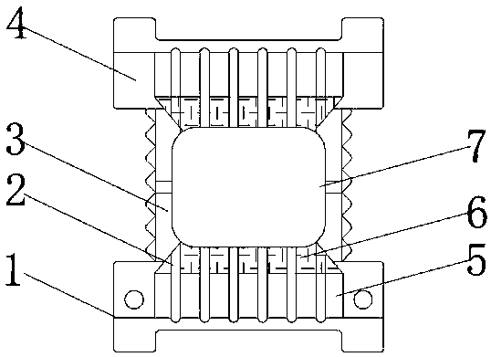
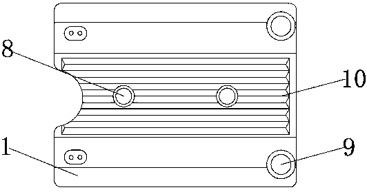
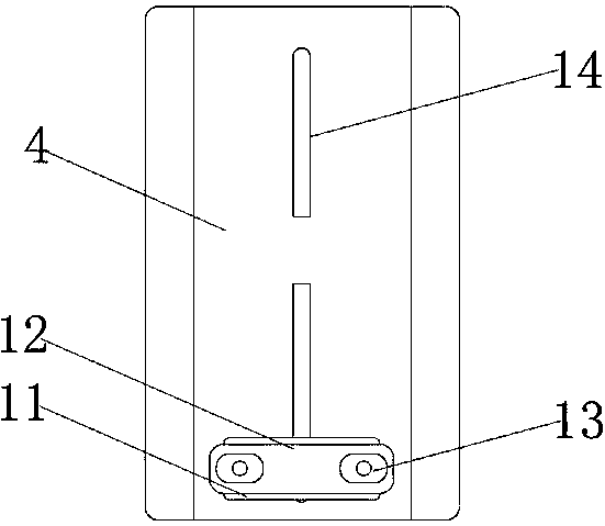
The invention discloses an intensive power bus duct system. The system comprises a first groove plate, a second groove plate and a U-shaped rod piece; accommodating grooves are formed in the surfacesof the first groove plate and the second groove plate; copper bars are uniformly mounted in the accommodating grooves; connecting plates are welded to the top end of the first groove plate and the bottom end of the second groove plate.; assembling screw holes are formed in the surfaces of the two sides of the first groove plate and two sides of the second groove plate; an assembling opening is formed in the bottom end of the first groove plate; an overhauling door plate is installed on the surface of the bottom end of the first groove plate on one side of the assembling opening through hinges;a groove opening is formed in a connecting plate; a control box is installed in the connecting plate of the first groove plate under the U-shaped rod piece; and a fixing plate is installed at the topend of the second groove plate. According to the bus duct system, a series of structures are arranged, so that the bus duct system can realize self-detection and remote control functions in the use process, and a bus is adjusted while maintenance and installation are facilitated.

Description

technical field [0001] The invention relates to the technical field of electric power intelligent control, in particular to an intensive power busway system. Background technique [0002] Due to its large power supply capacity, safety and reliability, and easy installation, the busway has been developed rapidly with the rapid development of China's engineering construction since it was introduced into my country in the 1980s. The process structure and material technology have been continuously innovated and developed. The performance and reliability of the product have been continuously improved, and it has become an important component of power distribution equipment, and it is the power transmission trunk line of building electrical. [0003] It’s just that in the actual use of the bus duct, affected by its structure and other factors, the bus will produce a series of problems, while the existing bus duct control system is relatively simple, the structure is relatively fixe...

Claims


Application Information

Patent Timeline
Patent Type & Authority Applications(China)
IPC IPC(8): H02G5/06H02G5/10
CPCH02G5/061H02G5/066H02G5/10
Inventor 冯洪刚
Owner 广东思东利电力科技有限公司
Why Eureka
Try Eureka