
Bidirectional electronic switch and control method thereof, and computer readable storage medium

A bidirectional electronic switch and bidirectional switching circuit technology, which is applied to electrical components, output power conversion devices, and AC power input to DC power output.

Pending Publication Date: 2020-02-21
HUNAN FUDE ELECTRICAL +1
View PDF1 Cites 2 Cited by
  • Summary
  • Abstract
  • Description
  • Claims
  • Application Information

AI Technical Summary

Problems solved by technology

[0003] The defect in the prior art is that before the bidirectional electronic switch changes the conduction direction of the bridge (that is, changes the direction of energy flow), it takes a certain amount of time for the energy in the thyristor to naturally discharge, causing the switching speed of the switch to be affected. limited, unable to cope with the extreme need to quickly switch the energy direction of the scene

Method used


Image

  • Bidirectional electronic switch and control method thereof, and computer readable storage medium
  • Bidirectional electronic switch and control method thereof, and computer readable storage medium
  • Bidirectional electronic switch and control method thereof, and computer readable storage medium

Examples


Embodiment Construction

[0037] Exemplary embodiments of the present disclosure will be described in more detail below with reference to the accompanying drawings. Although exemplary embodiments of the present disclosure are shown in the drawings, it should be understood that the present disclosure may be embodied in various forms and should not be limited by the embodiments set forth herein. Rather, these embodiments are provided for more thorough understanding of the present disclosure and to fully convey the scope of the present disclosure to those skilled in the art.

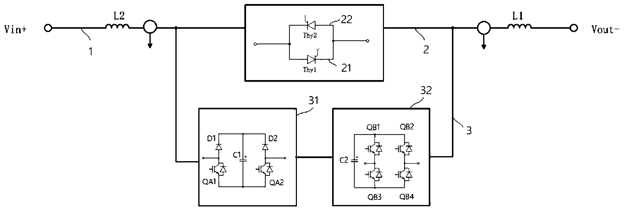
[0038] The bidirectional electronic switch of this embodiment is suitable for high-power scenarios such as 10kV / 5000A, such as figure 1 As shown, it mainly includes input terminal Vin+, output terminal Vout-, filter inductor L1, filter inductor L2, thyristor branch 2, and reverse voltage generation branch 3.

[0039] The input terminal Vin+ is connected in series with the filter inductor L1 and the filter inductor L2 in sequence, a...


PUM


Abstract

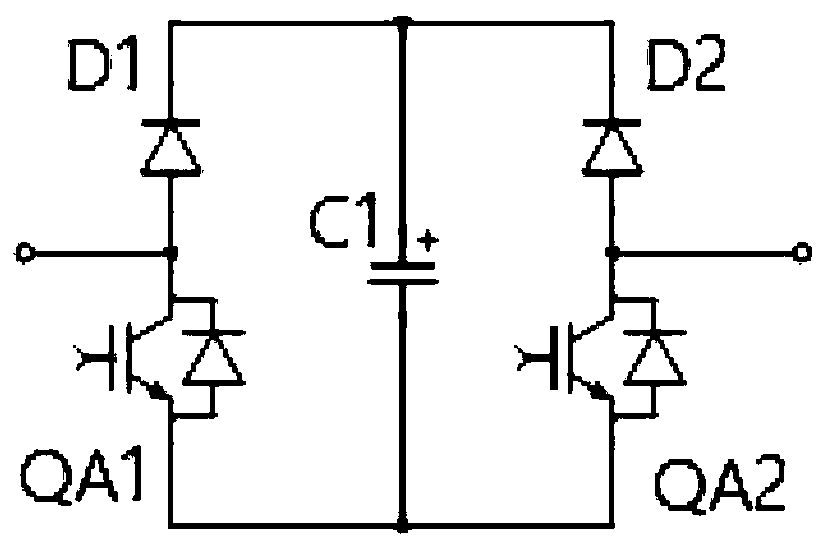
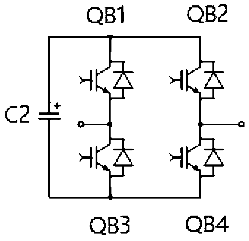
The invention relates to a bidirectional electronic switch and a control method thereof, and a computer readable storage medium, which are used for enabling the bidirectional electronic switch to quickly switch energy directions. The bidirectional electronic switch comprises a main loop, a silicon controlled rectifier branch and a reverse voltage generation branch, and the silicon controlled rectifier branch is connected in parallel with the reverse voltage generation branch and then connected in series in the main loop; the silicon controlled rectifier branch is provided with a forward branchand a reverse branch which are connected in parallel, the forward branch is provided with silicon controlled rectifiers Ty1 which are connected in series in the same conduction direction, and the reverse branch is provided with silicon controlled rectifiers Ty2 which are connected in series in the opposite conduction direction; the reverse voltage generation branch is provided with an H-bridge positive and negative voltage generation circuit connected in series in the reverse voltage generation branch, the H-bridge positive and negative voltage generation circuit is provided with an energy storage capacitor C2, and a switching tube QB1, a switching tube QB2, a switching tube QB3 and a switching tube QB4 which are sequentially connected in series to form a loop; one end of the energy storage capacitor C2 is connected with a contact between the switching tube QB1 and the switching tube QB2, and the other end of the energy storage capacitor C2 is connected with a contact between the switching tube QB3 and the switching tube QB4.

Description

technical field [0001] The invention relates to a bidirectional electronic switch, a control method thereof, and a computer-readable storage medium. Background technique [0002] The existing bidirectional electronic switch is basically as shown in document 200710019429.5, which uses high-power thyristors to form a bridge, and realizes bidirectional flow of energy by controlling the conduction direction of the bridge. [0003] The defect in the prior art is that before the bidirectional electronic switch changes the conduction direction of the bridge (that is, changes the direction of energy flow), it takes a certain amount of time for the energy in the thyristor to naturally discharge, causing the switching speed of the switch to be affected. Limits, unable to cope with the extreme need to quickly switch the energy direction of the scene. Contents of the invention [0004] The invention aims at enabling the bidirectional electronic switch to quickly switch the direction ...

Claims


Application Information

Patent Timeline
IPC IPC(8): H02M7/797
CPCH02M7/797
Inventor 李稳根廖晓斌
Owner HUNAN FUDE ELECTRICAL
Learn More