Fuel reduction rate output system, fuel reduction rate output method, and fuel reduction rate output program

A technology of output system and reduction rate, which is applied in the direction of control system, steam generation, lighting and heating equipment, etc., and can solve the problem that fuel reduction rate cannot be estimated

Active Publication Date: 2020-02-21
IDEMITSU KOSAN CO LTD +2
View PDF9 Cites 1 Cited by
  • Summary
  • Abstract
  • Description
  • Claims
  • Application Information

AI Technical Summary

Problems solved by technology

However, such a method requiring a performance test is devious, and the fuel reduction rate cannot be estimated in real time during operation.

Method used


Image

  • Fuel reduction rate output system, fuel reduction rate output method, and fuel reduction rate output program
  • Fuel reduction rate output system, fuel reduction rate output method, and fuel reduction rate output program

Examples


Embodiment Construction

[0021] Hereinafter, embodiments of the present invention will be described in detail based on the drawings. In addition, in all the drawings for explaining an embodiment, in principle, the same code|symbol is attached|subjected to the same part, and the repeated description is abbreviate|omitted. On the other hand, parts that are described with reference numerals in a certain drawing may be described using the same reference numerals without being shown again when describing other drawings.

[0022]

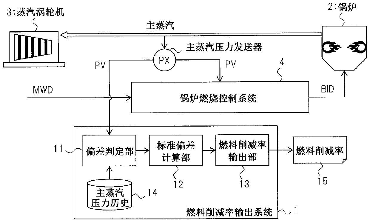
[0023] figure 1 It is a figure which shows the outline|summary of the structural example of the fuel reduction ratio output system which is one embodiment of this invention. exist figure 1 Among them, the control of the boiler 2 is carried out by the existing boiler combustion control system 4 . The boiler combustion control system 4 takes the load demand amount MWD as an input, and determines a boiler input command value BID which is a fuel input amount to the boiler by a f...


PUM


Abstract

A fuel reduction rate output system that calculates a fuel reduction rate affecting a fuel reduction measure, which is applied to a boiler combustion control system, wherein the fuel reduction rate output system has: a deviation determination unit that records the history of measured main steam pressures as a main steam pressure history, that calculates the deviation between the main steam pressure history and the measured main steam pressures, and that outputs the history of the main steam pressure for which the deviation is within a prescribed range as a history of control main steam pressure; a standard deviation calculation unit that calculates a standard deviation on the basis of the history of control main steam pressure output by the deviation determination unit; and a fuel reduction rate output unit that calculates a standard deviation improvement rate on the basis of the standard deviation calculated by the standard deviation calculation unit and that calculates and outputs the fuel reduction rate on the basis of a reference equation indicating the relationship between the standard deviation improvement rate and the fuel reduction rate.

Description

technical field [0001] The present invention relates to a technology for controlling the combustion of a boiler, and in particular to an effective fuel reduction rate output system, a fuel reduction rate output method, and a fuel reduction rate output program applied to calculate a fuel reduction rate obtained by improving boiler efficiency. technology. Background technique [0002] For example, when using boiler equipment to obtain energy, fuel (solid fuel such as coal, liquid fuel, or gaseous fuel) is supplied to the boiler (furnace) for combustion, and the heat is absorbed by a heat exchanger to generate steam to obtain thermal energy. The generated steam is converted from thermal energy into rotational motion by being supplied to a steam turbine, for example, and is used for power generation of a generator or the like. The amount of fuel input to the boiler is determined by the load demand (for example, power generation demand MWD (Mega Watt Demand), hereinafter, someti...

Claims


Application Information

Patent Timeline
Patent Type & Authority Applications(China)
IPC IPC(8): F22B35/00
CPCF22B35/00F22B35/18
Inventor 神柱大助谷口一德山下亨冈村雄治鹿岛伸浩首藤健一郎
Owner IDEMITSU KOSAN CO LTD
Why Eureka
Try Eureka