Hydraulic elevator with self-locking device

A self-locking device and lift technology, applied in the field of hydraulic lifts, can solve problems such as poor stability and large sinking, and achieve the effect of maintaining stability

Active Publication Date: 2020-02-25
江苏伙伴智能装备有限公司
View PDF8 Cites 4 Cited by
  • Summary
  • Abstract
  • Description
  • Claims
  • Application Information

AI Technical Summary

Problems solved by technology

[0006] The purpose of the present invention is to solve the problem of large sinking and poor stability of the existing scissor hydraulic lift after loading, and to provide a hydraulic lift with a self-locking device, which can not only provide a part of the support force for the lift, but also effectively Reduce the sinking amount after loading and ensure the stable operation of the elevator

Method used


Image

  • Hydraulic elevator with self-locking device
  • Hydraulic elevator with self-locking device
  • Hydraulic elevator with self-locking device

Examples


Embodiment 1

[0025] In order to make the present invention clearer, a hydraulic lift with a self-locking device of the present invention will be further described below in conjunction with the accompanying drawings. The specific embodiments described here are only used to explain the present invention, not to limit the present invention.

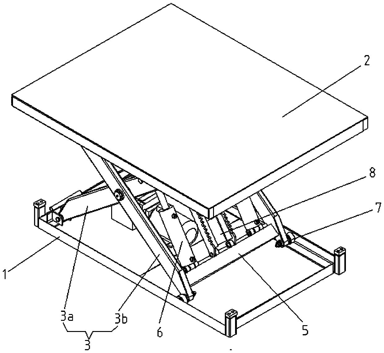
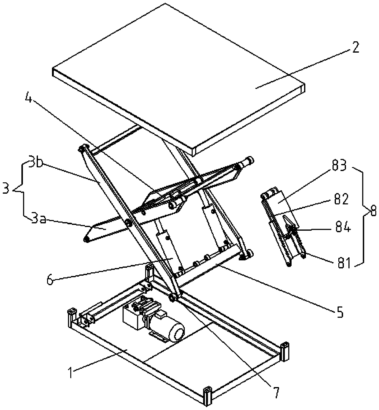
[0026] see figure 1 , figure 2 , a hydraulic lift with a self-locking device, including a base 1 and a lifting platform 2, a pair of scissor arms 3 are connected through a pulley block 7 between the two, and each scissor arm 3 is composed of an inner support rod 3a and an outer support rod 3a. The middle part of the support rod 3b is hinged, and a first connecting rod 4 is horizontally fixed between the middle parts of each pair of inner support rods 3a, and a second connecting rod 5 is horizontally fixed between the bottoms of each outer support rod 3b. A set of hydraulic cylinders 6 for providing lifting is hinged between the rod 4 and the second con...


PUM


Abstract

The invention relates to a hydraulic elevator with a self-locking device. The hydraulic elevator comprises a base (1) and a lifting platform (2). Shear fork arms (3) are connected between the base andthe lifting platform. Each shear fork arm is formed by connecting the middle of an inner support rod (3a) and the middle of an outer support rod (3b) in a hinged manner. A first connecting rod (4) ishorizontally fixed between the pair of inner support rods (3a). A second connecting rod (5) is horizontally fixed between the pair of outer support rods (3b). A set of hydraulic cylinders (6) and theself-locking device (8) are hinged between the first connecting rod (4) and the second connecting rod (5). The self-locking device (8) comprises a fixing seat (81), a connecting seat (82), a movableseat (83) and a cylinder (84) which are cooperatively used. The connecting seat (82) and the movable seat (83) are hinged to the first connecting rod (4). The fixing seat (81) is hinged to the secondconnecting rod (5). The hydraulic elevator with the self-locking device has the beneficial effects that the support force is provided, the sinking amount is reduced, and the equipment stability is ensured.

Description

technical field [0001] The invention relates to the technical field of hydraulic lift equipment, in particular to a hydraulic lift with a self-locking device. Background technique [0002] Hydraulic lifts are widely used in factory loading and unloading transportation, especially hydraulic lifts for lifting platforms. They are currently a very widely used vertical cargo transport equipment. They are popular among users for their low price, large load capacity and simple installation. However, hydraulic lifts have a big disadvantage: the sinking is very large after loading, which affects the entry and exit of goods. The main factors affecting the sinking of the hydraulic lift are the load capacity, the metal structure of the main body of the equipment, the oil cylinder and the processing accuracy of the equipment, etc. [0003] First of all, metal has the characteristics of elastic expansion and contraction. Under the influence of gravity after loading, the metal structure o...

Claims


Application Information

Patent Timeline
Patent Type & Authority Applications(China)
IPC IPC(8): B66F7/08B66F7/28
CPCB66F7/065B66F7/085B66F7/28
Inventor 杭孝文王加利张振凯
Owner 江苏伙伴智能装备有限公司
Why Eureka
Try Eureka