
Explosion-proof type plasma bulk reactor

A plasma and reactor technology, applied in the field of ion reactors, can solve problems such as inability to install and use, limitations of plasma technology promotion, and inability to meet regional explosion-proof requirements in places with high explosion-proof levels, to achieve release, improve explosion-proof effect, excellent The effect of explosion-proof performance

Pending Publication Date: 2020-02-28
杭州卓天科技有限公司
View PDF0 Cites 0 Cited by
  • Summary
  • Abstract
  • Description
  • Claims
  • Application Information

AI Technical Summary

Problems solved by technology

However, due to the essence of its purification principle, plasma technology cannot meet the regional explosion-proof requirements in places with high explosion-proof levels. As a result, many companies with explosion-proof requirements have lost the right to choose plasma technology, and the promotion of plasma technology has also been greatly affected. limitations
[0003] At present, the low-temperature plasma waste gas purification technology commonly used in the market generally uses two discharge forms: pulse discharge and DBD dielectric barrier discharge. The phenomenon of fire, so the traditional low-temperature plasma bulk reactor has the possibility of igniting combustible gas and causing an explosion in theory, but the strength of the traditional plasma bulk reactor itself is not enough to restrain the shock wave generated by the internal explosion, and the purification equipment is in During the operation, the internal space of the bulk reactor is in direct contact with the exhaust gas pollutant medium, so the traditional plasma bulk reactor does not have the conditions to operate in the explosion-proof area
[0004] Existing anti-explosion measures for plasma bulk reactors mainly use instruments to measure the concentration of combustible gas and ambient temperature to prevent in advance, rather than solving the problem of explosion-proof from the equipment itself, and it cannot be installed and used in places with high explosion-proof levels.

Method used


Image

  • Explosion-proof type plasma bulk reactor
  • Explosion-proof type plasma bulk reactor
  • Explosion-proof type plasma bulk reactor

Examples


Embodiment Construction

[0026] The technical solutions of the embodiments of the present invention will be explained and described below in conjunction with the accompanying drawings of the embodiments of the present invention, but the following embodiments are only preferred embodiments of the present invention, not all of them. Based on the examples in the implementation manners, other examples obtained by those skilled in the art without making creative efforts all belong to the protection scope of the present invention.

[0027] In the following description, terms such as "inner", "outer", "upper", "lower", "left", "right" etc. appearing to indicate orientation or positional relationship are only for the convenience of describing the embodiment and simplifying the description, rather than Nothing indicating or implying that a referenced device or element must have a particular orientation, be constructed, and operate in a particular orientation should therefore not be construed as limiting the inv...


PUM


Abstract

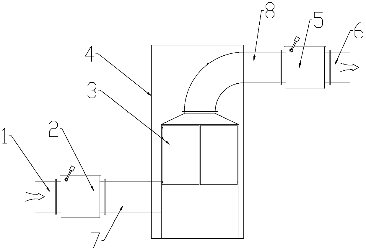
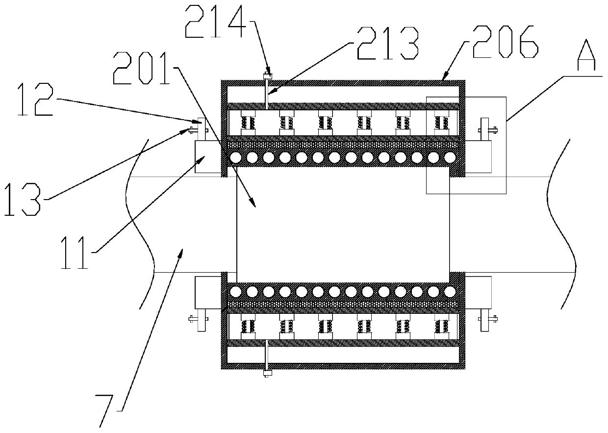
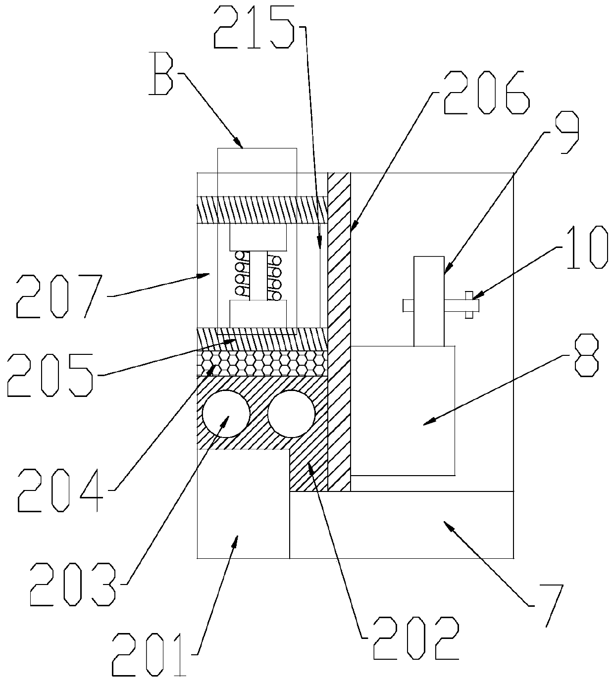
The invention discloses an explosion-proof type plasma bulk reactor. The device comprises a waste gas inlet end, a gas inlet pipe, a plasma bulk reactor inner cavity, a gas outlet pipe and a waste gasoutlet end. The gas inlet pipe is mounted at the lower end of the inner cavity of the plasma bulk reactor. The gas outlet pipe is mounted at the upper end of the inner cavity of the plasma bulk reactor. The waste gas inlet end is arranged at one end, away from the inner cavity of the plasma bulk reactor, of the gas inlet pipe. The waste gas outlet end is arranged at one end, away from the inner cavity of the plasma bulk reactor, of the gas outlet pipe. The gas inlet pipe is provided with a gas inlet explosion-proof valve, the gas outlet pipe is provided with a gas outlet explosion-proof valve, and the periphery of the inner cavity of the plasma bulk reactor is sleeved with an explosion-proof box. The plasma bulk reactor has excellent explosion-proof performances.

Description

technical field [0001] The invention relates to the technical field of plasma reactors, in particular to a flameproof plasma bulk reactor. Background technique [0002] With the continuous development of the environmental protection industry, a variety of treatment technologies have emerged for the treatment of odor and VOCs exhaust gas. Plasma technology, as one of the most widely used purification technologies, is used in the treatment of exhaust gas in many industries, and Plasma purification equipment in the true sense also has a more obvious purification effect on exhaust gas, especially for pollutants that cannot be degraded and treated by conventional processes. However, due to the essence of its purification principle, plasma technology cannot meet the regional explosion-proof requirements in places with high explosion-proof levels. As a result, many companies with explosion-proof requirements have lost the right to choose plasma technology, and the promotion of plas...

Claims


Application Information

Patent Timeline
Patent Type & Authority Applications(China)
IPC IPC(8): B01D53/32
CPCB01D53/323B01D2257/708B01D2259/818
Inventor 方洲郭炎鹏李玉柱于海洋刘崇惠张灿朋赵安志陈芷豪
Owner 杭州卓天科技有限公司
Learn More