Four-axis double-sided engraving machine

An engraving machine and double-sided technology, applied in the field of engraving machines, can solve problems such as the reduction of engraving accuracy and the influence of product details on the appearance, and achieve the effect of preventing shaking

Pending Publication Date: 2020-02-28
厦门特雕科技有限公司
View PDF2 Cites 6 Cited by
  • Summary
  • Abstract
  • Description
  • Claims
  • Application Information

AI Technical Summary

Problems solved by technology

However, the existing four-axis engraving machine clamps the workpiece blank by clamping the two ends of the equipment clamping mechanism towards each other, and the blank is completely suspended during processing, especially for blanks with large surface size and many engraving details. , Different degrees of jitter will occur during engraving, which will reduce the engraving accuracy and affect the appearance of product details

Method used


Image

  • Four-axis double-sided engraving machine
  • Four-axis double-sided engraving machine
  • Four-axis double-sided engraving machine

Examples


Embodiment 1

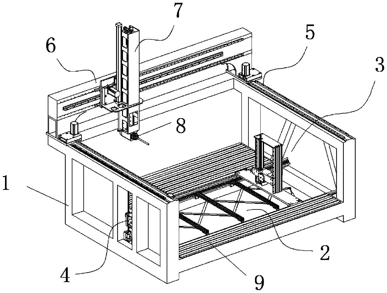
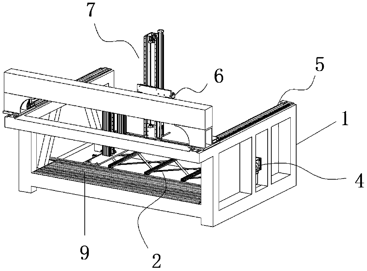
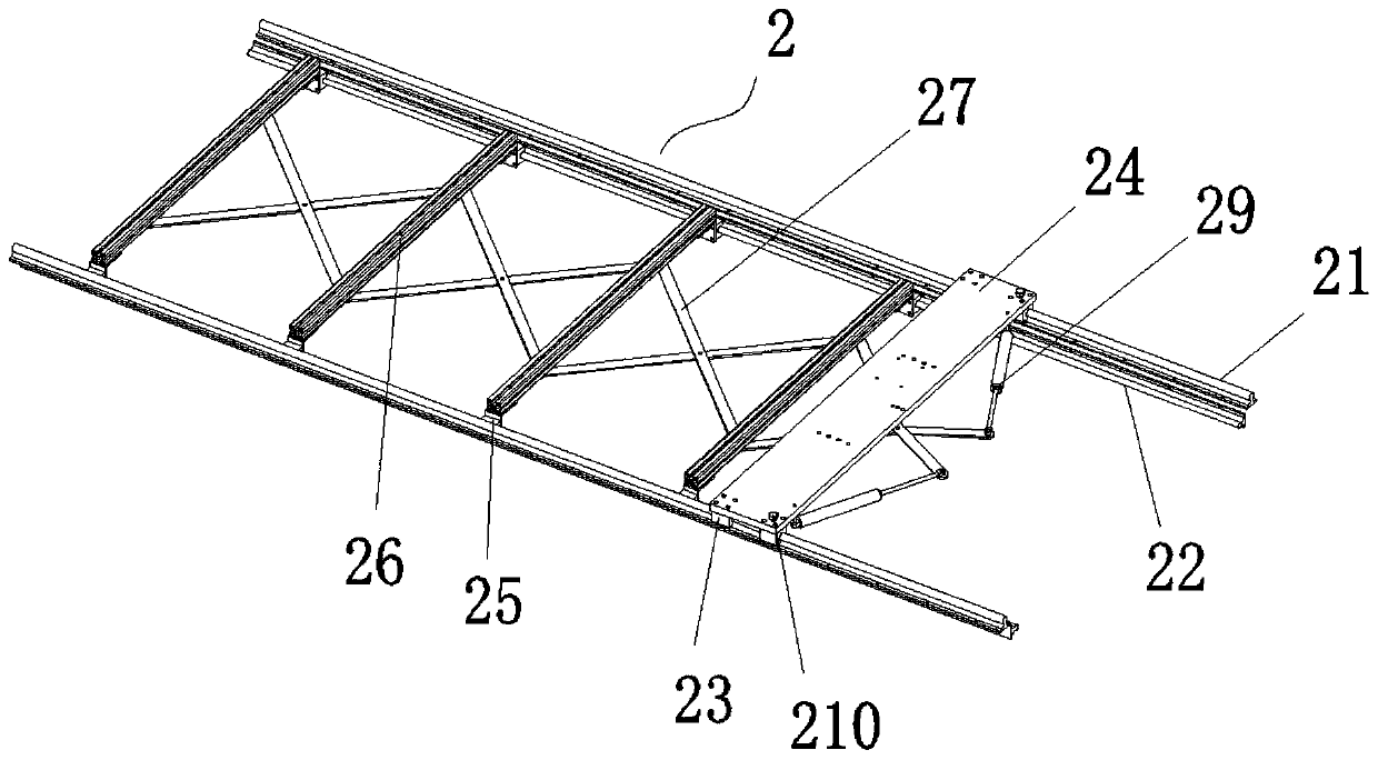
[0055]For double-sided engraving processing: the engraving main shaft 8 is installed below the rear side wall of the Z-axis elevating frame 68, and the cutter installed at the output end of the engraving main shaft 8 is installed vertically. After lifting the pressing plate 36 and the flipping plate 46 to a certain height synchronously, the double-sided engraved thick plate-shaped blank is clamped as described above. After the clamping is completed, the scissor telescopic frame 27 is launched, and the workpiece is lifted and pressed. Structure 3 and The workpiece lifting and turning mechanism 4 drives the blank down to the bottom surface and fits the top of the scissors telescopic frame 27, and the top surface processing can be started. After the top surface is processed, the blank is lifted again by the workpiece lifting and pressing structure 3 and the workpiece lifting and turning mechanism 4 Then the scissors telescopic frame 27 is combined, and then the blank is turned 180...

Embodiment 2

[0057] For cylinder engraving processing: the engraving main shaft 8 is installed on the bottom of the Z-axis elevating frame 68, and the cutting tool installed on the output end of the engraving main shaft 8 is installed horizontally forward. After lifting the pressure plate 36 and the turning plate 46 to a certain height synchronously, the double-sided engraved cylindrical blank is clamped as described above, and can be processed after clamping. Since the horizontal dimension of the cylindrical sculpture is equivalent to the vertical dimension, One-sided deflection is not easy to occur, and the jitter is not obvious during processing, and the workpiece lifting and pressing structure 3 and the workpiece lifting and turning mechanism 4 may be required to drive the blank to rotate during processing to cooperate with the spindle for processing, so the shears are generally not used in this embodiment. Fork telescopic frame 27 carries out auxiliary support.


PUM


Abstract

The invention discloses a four-axis double-sided engraving machine in the technical field of engraving machines. The four-axis double-sided engraving machine comprises a main frame, wherein a telescopic supporting mechanism is arranged at the bottom of an inner cavity of the main frame; the telescopic supporting mechanism can slide and adjust leftward and rightward relative to the main frame; a workpiece lifting and pressing structure is arranged at the top of the telescopic supporting mechanism; a workpiece lifting and overturning mechanism is arranged at the left side of the main frame; a Y-axis moving mechanism is arranged at the top of the main frame; an X-axis moving mechanism is arranged at the top moving end of the Y-axis moving mechanism; the front moving end of the X-axis moving mechanism is provided with a Z-axis moving mechanism; and a carving spindle is arranged below the front lifting end of the Z-axis moving mechanism. After the four-axis double-sided engraving machine isunfolded by the telescopic support mechanism, the four-axis double-sided engraving machine can be attached to the bottom surface of a blank with a larger surface size and more engraving details to assist in supporting the blank, so as to prevent shaking in the processing process from affecting the appearance of product details.

Description

technical field [0001] The invention relates to the technical field of engraving machines, in particular to a four-axis double-sided engraving machine. Background technique [0002] Foam engraving machine, the main structure is composed of a fixed bed frame, a vertically movable gantry, a horizontally movable head assembly, a vertically movable head, a spindle and a tool, to realize the foam engraving process of the whole machine, in which the fixed bed machine The frame adopts a high-strength square tube structure to improve the overall strength and structural stability of the frame to improve the accuracy of engraving processing. The Y-axis guide rail is laid flat on the side beam of the frame to effectively improve the stability of the gantry beam. The foam workpiece is clamped on the bed frame, and the foam carving function is realized through the gantry beam and the head part. Foam engraving machine is a kind of CNC equipment for professional processing of foam. It be...

Claims


Application Information

Patent Timeline
Patent Type & Authority Applications(China)
IPC IPC(8): B26D1/12B26D5/06B26D7/00B26D7/02B26D7/26
CPCB26D1/12B26D5/06B26D7/00B26D7/02B26D7/2628
Inventor 吴天军
Owner 厦门特雕科技有限公司
Why Eureka
Try Eureka