Three-layer diversion material storage die head device for blow molding machine

A blow molding machine and die head technology, which is applied in the field of three-layer diversion material storage type die head device, can solve the problems of affecting the blank, high energy consumption, material denaturation, etc., to avoid material denaturation, reduce manufacturing costs, simplify structure effect

Active Publication Date: 2021-11-05
SUZHOU TONGDA MACHINERY
View PDF10 Cites 0 Cited by
  • Summary
  • Abstract
  • Description
  • Claims
  • Application Information

AI Technical Summary

Problems solved by technology

[0005] According to professional knowledge, the three-layer plastic needs to be guaranteed by the corresponding die head device. For this, please refer to the "three-layer plastic molding machine" recommended by the Chinese patent CN202062631B. Technical effect, but this patent has the following shortcoming: one, due to the need to adopt respectively independent inner, middle and outer three material storage forming die heads respectively adopts three mold cover mechanisms, inner, middle, outer, mold body, i.e. Inner, middle and outer layers of material storage mold body, middle layer forming die opening, outer layer forming die opening and inner layer forming die opening are relatively loose in structure, not only bulky, but also high in manufacturing cost; second, because the three sets of mechanisms all It needs to be equipped with a heating device, that is, heaters are installed outside the inner, middle and outer layer material storage molds, so the energy consumption is large; third, when the material blanks such as the middle layer material blank and the outer layer material The entrance of the middle layer blank and the entrance of the outer layer blank mentioned in the patent will encounter greater resistance when they are transported inwardly to the storage cavity at the injection port, and the friction force is large, so it is difficult for the middle layer blank to fully surround The inner layer blank, and the outer layer blank are also difficult to completely surround the middle layer blank, and there will inevitably be material leakage between layers; Each head has an independent heater, so it is difficult to control the temperature of the billet, which is easy to cause material denaturation, affecting the billet and affecting the quality of the molten billet

Method used


Image

  • Three-layer diversion material storage die head device for blow molding machine
  • Three-layer diversion material storage die head device for blow molding machine
  • Three-layer diversion material storage die head device for blow molding machine

Examples


Embodiment Construction

[0022] In order to understand the technical essence and beneficial effects of the present invention more clearly, the applicant will describe in detail the following examples, but the descriptions of the examples are not intended to limit the solutions of the present invention. Equivalent transformations that are only formal but not substantive should be regarded as the scope of the technical solution of the present invention.

[0023] In the following descriptions, all concepts related to directionality or orientation of up, down, left, right, front and back are based on figure 1 The current position is a reference, so it cannot be understood as a special limitation on the technical solution provided by the present invention.

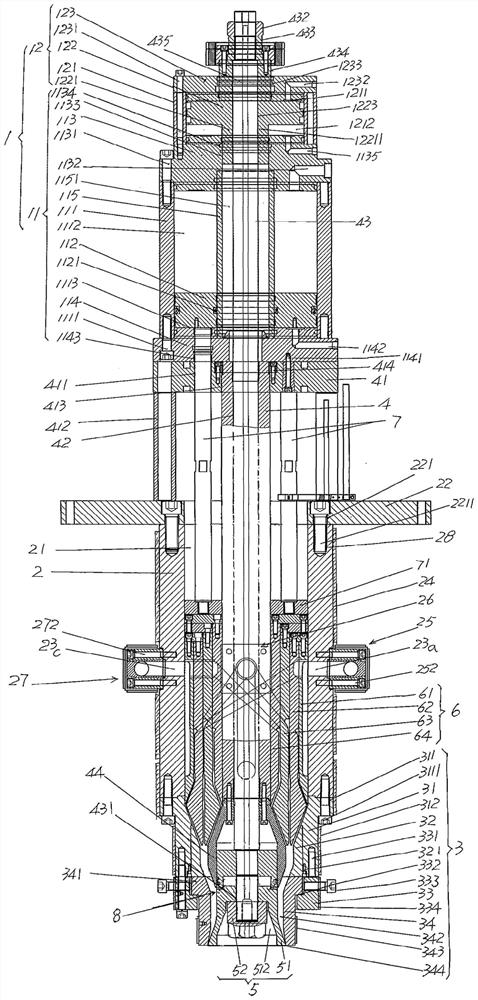
[0024] See figure 1 and combine Figure 4 , showing a driving mechanism 1; showing a shooting cylinder liner 2, which has a shooting cylinder liner cavity 21, and the upper part of the shooting cylinder liner 2 is fixed with a die support plate 22, ...


PUM


Abstract

A three-layer diversion material storage type die head device for a blow molding machine, including a driving mechanism; a shooting cylinder liner; a mold sleeve mechanism; a material storage core tube; a die mechanism; The push rod is characterized in that: the compound molten billet injection mechanism includes the first, second, third and fourth push cylinders, the first push cylinder is set in the cavity of the injection cylinder, and the first push cylinder is set on the outer wall The outer layer, the middle layer and the inner layer material guide groove of the cylinder liner, the second pushing cylinder is set in the cavity of the first pushing cylinder liner and there is an outer layer melt guiding device on the outer wall, and the third pushing cylinder liner is set at the second In the cavity of the second pushing cylinder, there is a middle melt guiding device on its outer wall, and the fourth pushing cylinder is set in the cavity of the third pushing cylinder, and there is an inner melting guiding device on its outer wall, and an upper end surface The upper pressing ring is fixed; the lower end of the material storage core tube extends into the cavity of the fourth pushing cylinder; the lower end of a group of injection push rods is fixed with the pressing ring of the pushing rod. Advantages: Simplify the structure; save energy; avoid material leakage, prevent parison cross-linking and ideal efficiency of color change on demand.

Description

technical field [0001] The invention belongs to the technical field of blow molding machinery, and in particular relates to a three-layer diversion material storage type die head device of a blow molding machine. Background technique [0002] The aforementioned blow molding machine is equipment for processing hollow plastic containers, such as filling pharmaceutical and chemical raw materials, oil products, various additives, various solvents, additives, packaging barrels for hazardous chemicals, water tanks, oil tanks, etc. The fuel tank of the vehicle, etc. Since the blow molding mechanism of the blow molding machine belongs to the known technology, for example, please refer to the Chinese patents CN201941151U (automatic hollow molding machine for plastic containers) and CN202162995U (automatic hollow molding machine for large plastic containers), etc., so the applicant No longer. [0003] The aforementioned die head device is an important part of the blow molding machin...

Claims


Application Information

Patent Timeline
Patent Type & Authority Patents(China)
IPC IPC(8): B29C48/335B29C48/48B29C48/17B29C48/18B29C49/04B29C49/22
CPCB29C49/041B29C49/22B29C48/17B29C48/18B29C48/335B29C48/48
Inventor 徐文良何建领肖志林李明刘俊
Owner SUZHOU TONGDA MACHINERY
Why Eureka
Try Eureka