Insertion-rod-type vehicle stop device for mine

A technology for mining and inserting rods, which is applied in the direction of mandatory railway stopper, transportation and packaging, railway car body parts, etc., can solve the problems of increased workload, inconvenience, accidental injury to staff, etc., and achieves convenient operation and use effect. Good results

Inactive Publication Date: 2020-02-28
王栋
View PDF0 Cites 0 Cited by
  • Summary
  • Abstract
  • Description
  • Claims
  • Application Information

AI Technical Summary

Problems solved by technology

[0003] In actual operation, after the staff pulls out the baffle rod from the base, they will discard the baffle rod at will. If it bounces up, it is likely to accidentally injure the staff. On the other hand, the irregular random placement of the stopper bar is very likely to stumble other workers passing by here. Third, when the car needs to be blocked again, the stopper bar should be reinserted into the base At this time, the baffle lever that is discarded may not be found in time, thus wasting too much time to find the baffle lever
[0004] In addition, during driving, since the baffle rod is pulled out from the base, the baffle rod placement cylinder in the base is in an upwardly open state. objects, causing the stop rod to not be inserted into the base normally, thus affecting the normal use of the car stop device, so it is necessary to clean up the sundries in the stop rod placement cylinder in time
Because the baffle rod placement cylinder has a certain depth, it is inconvenient for the staff to directly operate, so it is necessary to process tools with long handles, which undoubtedly increases the workload and improves the production cost, and because the baffle rod placement cylinder is deep, even if With a tool with a long handle, it is still inconvenient to operate, time-consuming and labor-intensive, and the cleaning effect is not very good

Method used


Image

  • Insertion-rod-type vehicle stop device for mine
  • Insertion-rod-type vehicle stop device for mine
  • Insertion-rod-type vehicle stop device for mine

Examples


Embodiment Construction

[0028] The principles and features of the present invention are described below in conjunction with the accompanying drawings, and the examples given are only used to explain the present invention, and are not intended to limit the scope of the present invention.

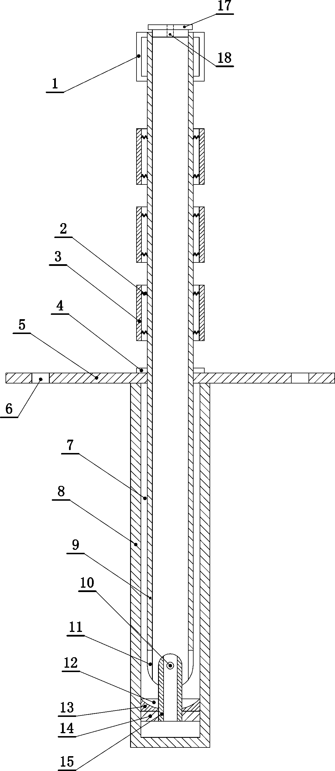
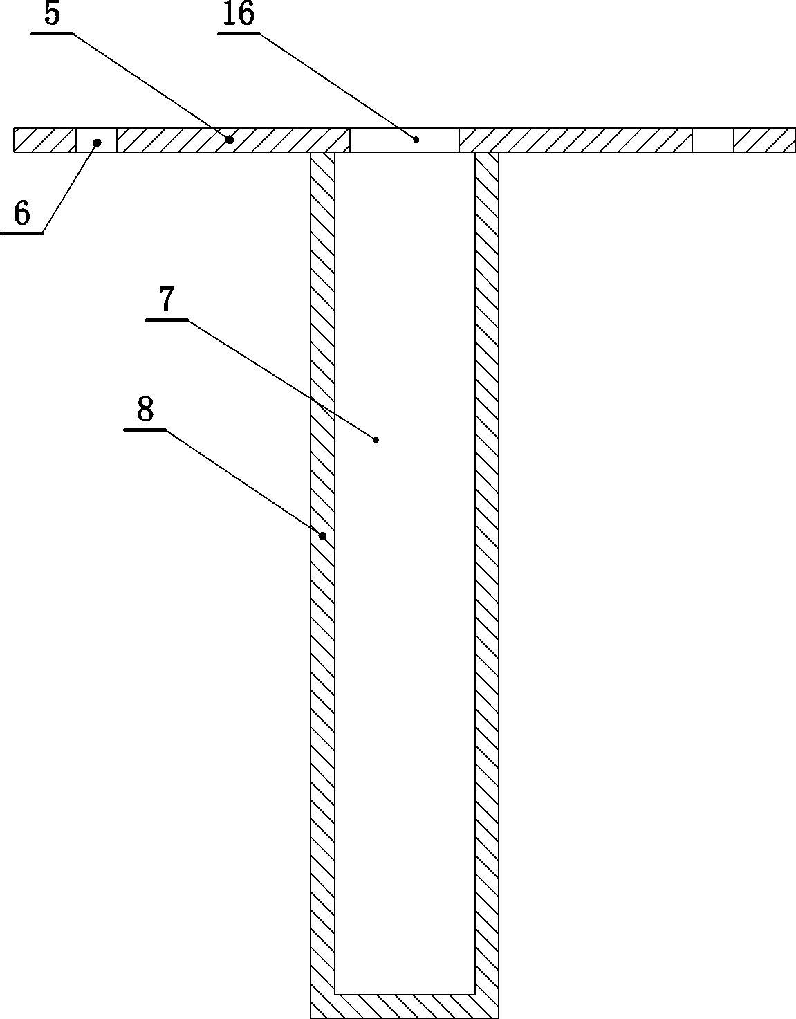
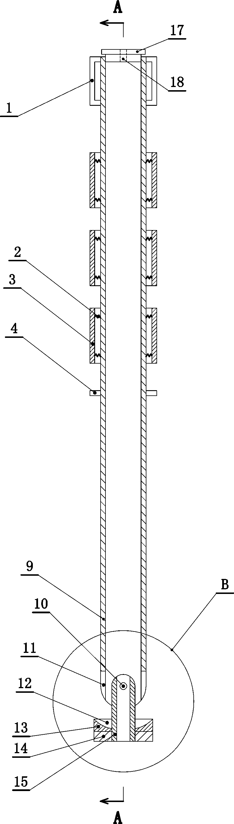
[0029] Such as Figure 1 to Figure 8 As shown, a plug-in type mine car stop device includes a base, and the base includes a mounting plate (5), which is installed horizontally, and the mounting plate (5) is fixedly installed between two rails for the mine car On the ground passing along the way, there are fixing holes (6) arranged transparently up and down on the installation fixing plate (5), and a plurality of fixing holes (6) are set on the installation fixing plate (5) around the guide limit hole (16). ), and the fixing plate (5) can be easily fixed on the ground through the fixing hole (6).

[0030] The installation fixed plate (5) is provided with a guide limit hole (16) transparently set up and down, the gui...


PUM


Abstract

The invention relates to an insertion-rod-type vehicle stop device for a mine. The horizontal cross section outline of a stop lever insertion chamber is oval, the horizontal projection of a guide limit hole is located in the horizontal projection range of the stop lever insertion chamber, and a stop lever is movably inserted in the stop lever insertion chamber in the up-down mode and penetrates through the guide limit hole. The lower end of the stop lever is located in the stop lever insertion chamber, the upper end of the stop lever is located above a mounting fixing plate, and the stop leveris hollow and through up and down and simultaneously provided with upward and downward openings. A connection pipe is hinged to the lower end of the stop lever and is through up and down, the upper end of the connection pipe is hinged into the lower end of the stop lever, and a guide limit block is fixedly connected to the lower end of the connection pipe and movably arranged in a stop lever placement cylinder in an up-down mode. The connection pipe penetrates through the guide limit block in an up-down mode, the lower end of the stop lever is provided with a spiral containing groove, the stop lever is upwards lifted relative to the stop lever placement cylinder, the guide limit block abuts against the lower face of the mounting fixing plate, the stop lever is horizontal and is flat placed, and the connection pipe is located in the spiral containing groove.

Description

technical field [0001] The invention relates to a mine device, in particular to a plug-in type mine car stop device. Background technique [0002] In coal mining enterprises, in order to ensure safe production, it is necessary to achieve three gears on one slope, and the third gear includes a car stopper. The stop rod placement tube), the base is installed and fixed on the place where the mine car passes between the two rails, when the car needs to be blocked, the stop rod is inserted into the base, so that the stop rod is in a standing state, and it is used to block the mine car sports car. When driving, the stop bar is pulled out from the base, the track is in an open state, and the mine car can move normally. [0003] In actual operation, after the staff pulls out the baffle rod from the base, they will discard the baffle rod at will. If it bounces up, it is likely to accidentally injure the staff. On the other hand, the irregular random placement of the stopper bar is ...

Claims


Application Information

Patent Timeline
Patent Type & Authority Applications(China)
IPC IPC(8): B61K7/16
CPCB61K7/16
Inventor 王志营
Owner 王栋
Why Eureka
Try Eureka