Eureka AIR delivers breakthrough ideas for toughest innovation challenges, trusted by R&D personnel around the world.

Heat-phase separation solid residue discharged material cooling dust removal device and method

A solid residue and thermal phase separation technology, applied in packaging, transportation and packaging, loading/unloading, etc., can solve the problems of insufficient dust suppression, uneven mixing, large water consumption, etc., to reduce temperature, improve heat transfer efficiency, The effect of reducing dosage

Pending Publication Date: 2020-02-28
RUIJIE ENVIRONMENTAL PROTECTION TECH CO LTD
View PDF0 Cites 2 Cited by
  • Summary
  • Abstract
  • Description
  • Claims
  • Application Information

AI Technical Summary

Problems solved by technology

The traditional sprinkler dust suppression device has large water consumption, uneven mixing, water vapor carries dust and causes secondary pollution, and dust suppression is insufficient

Method used


Image

  • Heat-phase separation solid residue discharged material cooling dust removal device and method
  • Heat-phase separation solid residue discharged material cooling dust removal device and method

Examples


Embodiment Construction

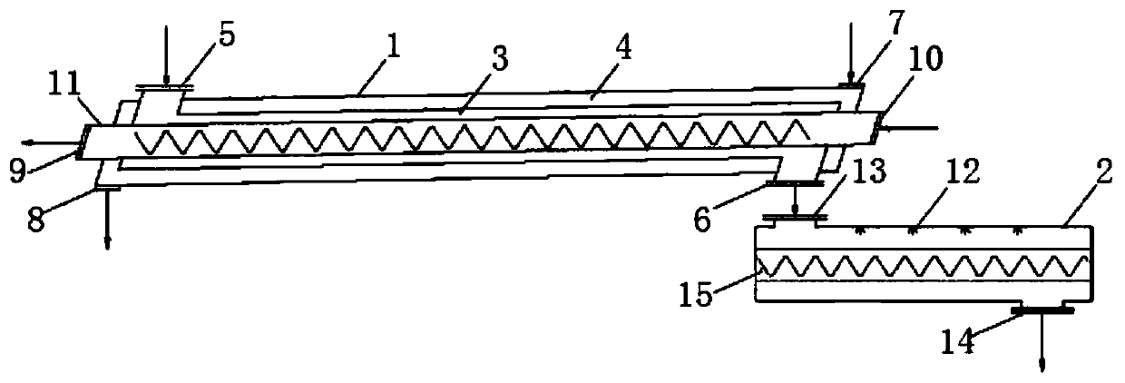
[0018] Such as Figures 1 to 2 As shown, a thermal phase separation solid residue discharge cooling and dedusting device includes a discharge screw device 1 and a discharge spray screw device 2, the discharge screw device 1 is connected to the discharge spray screw device 2, the The discharge screw device 1 is provided with a first screw shaft 11, a material cavity 3 and a jacket cavity 4, the first screw shaft 11 is covered with a material cavity 3, the jacket cavity 4 is set outside the material cavity 3, and the first screw The shaft 11 is used to transport the material in the material chamber 3. Further preferably, the first screw shaft 11 is provided with paddles, the paddles are in multiple groups, and the multiple groups of paddles are helically evenly distributed on the first screw shaft 11. On the screw shaft 11. One end of the material chamber 3 is provided with a first feed port 5, the first feed port 5 extends through the jacket chamber 4 to the outside of the jac...


PUM


Abstract

The invention discloses a heat-phase separation solid residue discharged material cooling dust removal device. The heat-phase separation solid residue discharged material cooling dust removal device comprises a discharged material spiral device and a discharged material spraying spiral device. The discharged material spiral device and the discharged material spraying spiral device are connected with each other. The discharged material spiral device comprises a first spiral shaft, a material cavity and a clamping sleeve cavity. The material cavity sleeves the first spiral shaft, and the clamping sleeve cavity sleeves the material cavity. The first spiral shaft is used for conveying materials in the material cavity. A first material inlet is formed in one end of the material cavity, passes through the clamping sleeve cavity and extends to the exterior of the clamping sleeve cavity. A first material outlet is formed in the other end of the material cavity, passes through the clamping sleeve cavity and extends to the exterior of the clamping sleeve cavity. A first water inlet is formed in one end of the clamping sleeve cavity, and a first water outlet is formed in the other end of theclamping sleeve cavity. Spraying assemblies are arranged in the discharged material spraying spiral device and used for spraying water to materials. The heat-phase separation solid residue dischargedmaterial cooling dust removal device has the beneficial effects that the cooling operation is conducted before the high-temperature materials are subjected to water spraying humidification and dust removal, the consumption of the spraying water is reduced, and the phenomenon that due to the fact that the moisture carries the dust, the serious secondary pollution happens is avoided.

Description

technical field [0001] The invention relates to the technical field of thermal phase separation treatment, in particular to a thermal phase separation solid residue discharging cooling and dedusting device and method. Background technique [0002] With its safety, environmental protection, high efficiency and thorough technical advantages, thermal phase separation technology has received more and more attention and industry recognition in the field of organic pollution waste treatment, and has become the most promising waste treatment technology at present. The temperature of solid residue in thermal phase separation technology is usually 300-500°C, and direct discharge of high-temperature solid residue will generate a large amount of dust and cause pollution. At present, in order to reduce the amount of dust on the job site, the material is usually directly sprayed to reduce dust at the discharge port. The traditional sprinkler dust suppression device has a large water con...

Claims


Application Information

Patent Timeline
Patent Type & Authority Applications(China)
IPC IPC(8): B65G69/20B65G69/18B65G33/24
CPCB65G69/20B65G69/188B65G33/24
Inventor 张哲娜梁仁刚林慧丽闫亚丽金兆迪
Owner RUIJIE ENVIRONMENTAL PROTECTION TECH CO LTD
Why Eureka
Eureka Blog
Learn More