
A positioning mechanism for textile cloth winding device

A technology of positioning mechanism and winding device, which is applied in the cutting of textile materials, textiles and papermaking, thin material processing, etc., can solve the problems of affecting the cloth rolling process, consuming manpower and time, and the limited length of a single paper tube core, etc., to achieve Save time and physical strength, facilitate the cutting process, and avoid the effect of cutting the staff

Active Publication Date: 2021-06-01
永春县产品质量检验所福建省香产品质量检验中心国家燃香类产品质量监督检验中心福建
View PDF0 Cites 0 Cited by
  • Summary
  • Abstract
  • Description
  • Claims
  • Application Information

AI Technical Summary

Problems solved by technology

[0005] Aiming at the deficiencies of the prior art, the present invention provides a positioning mechanism for a textile cloth winding device, which has the advantages of being convenient to use, and solves the need to set a paper core on the winding shaft when the cloth is prepared, but a single paper The length of the core is limited. Generally, two or three paper cores are combined into one. It is necessary to set multiple cores and then cut off the excess paper cores manually with a saw. This method consumes manpower and time and affects the process of rolling cloth.

Method used


Image

  • A positioning mechanism for textile cloth winding device
  • A positioning mechanism for textile cloth winding device
  • A positioning mechanism for textile cloth winding device

Examples


Embodiment Construction

[0026] The following will clearly and completely describe the technical solutions in the embodiments of the present invention with reference to the accompanying drawings in the embodiments of the present invention. Obviously, the described embodiments are only some, not all, embodiments of the present invention. Based on the embodiments of the present invention, all other embodiments obtained by persons of ordinary skill in the art without making creative efforts belong to the protection scope of the present invention.

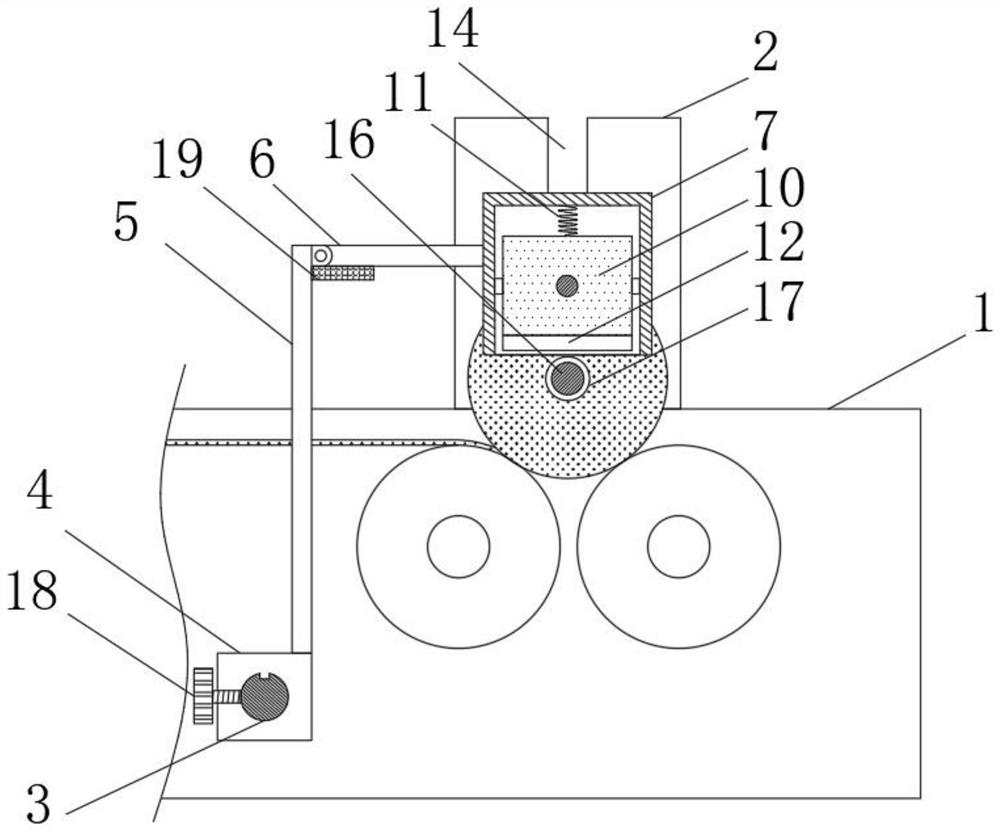
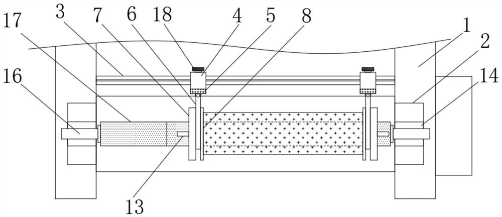
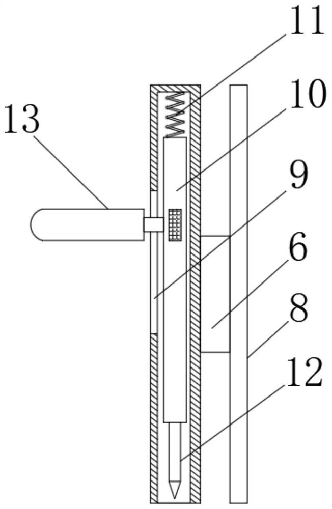
[0027] see Figure 1-4 , a positioning mechanism for a textile fabric winding device, including a base 1, the number of the bases 1 is set to two, the two bases 1 are symmetrically distributed, the surface of the base 1 is fixedly connected with a support seat 2, and the two bases A slide bar 3 is arranged between the seats 1, and the two ends of the slide bar 3 are respectively fixedly connected with the two bases 1. Two positioning mechanisms are arranged on...


PUM


Abstract

The invention relates to the field of textile technology, and discloses a positioning mechanism for a textile cloth winding device, comprising a base, the number of the bases is set to two, the two bases are symmetrically distributed, and the bases A support base is fixedly connected to the surface, a sliding rod is arranged between the two bases, the two ends of the sliding rod are respectively fixedly connected to the two bases, and two positioning mechanisms are arranged on the sliding rod, and the positioning mechanisms include The sleeve is slidably connected with the sliding rod, and the top of the sleeve is fixedly connected with a vertical plate. The positioning mechanism used in the textile fabric winding device is provided with a box body on the positioning baffle, and the sliding plate and the blade in the box can be moved down by pressing the handle. Compared with the existing manual sawing method, the paper tube core cutting is more time-saving and labor-intensive, reduces the impact on the winding process, and at the same time makes the incision on the edge of the paper tube core more tidy.

Description

technical field [0001] The invention relates to the technical field of textiles, in particular to a positioning mechanism for a textile cloth winding device. Background technique [0002] At present, the textile and cloth industry uses cloth rolling machines for cloth winding in production. It is suitable for round packaging of non-woven fabrics, foam, leather, paper, reflective materials, acetate cloth, reinforcing tape, conductive cloth and other materials. For the repeated rolling before cutting the bundles of fabrics, generally the paper core is set on the winding shaft first, and then the two ends of the winding shaft are respectively put into the slots on both sides of the winding machine, and the motor system drives the bottom of the winding shaft. The power roller rotates, and then drives the winding shaft to rotate to realize the roll material. Because the width of the fabric is different, two positioning baffles are generally provided to limit the positions of the ...

Claims


Application Information

Patent Timeline
Patent Type & Authority Patents(China)
IPC IPC(8): B65H18/20B65H18/02B65H19/30B65H19/26D06H7/00
CPCB65H18/028B65H18/20B65H19/26B65H19/30B65H2701/1133B65H2701/174D06H7/00
Inventor 方斌斌
Owner 永春县产品质量检验所福建省香产品质量检验中心国家燃香类产品质量监督检验中心福建
Learn More