Vehicle barrier rod device based on security and defense engineering

A technology of safety precautions and traffic barriers, which is applied to roads, road signs, traffic signals, etc., can solve problems such as deformation of traffic barriers, easy deformation, and reduced service life, so as to prolong the use time, reduce damage, and facilitate The effect of installation

Inactive Publication Date: 2020-02-28
合肥森弗卡电子科技有限公司
View PDF7 Cites 0 Cited by
  • Summary
  • Abstract
  • Description
  • Claims
  • Application Information

AI Technical Summary

Problems solved by technology

[0002] In the roads or entrances and exits of various public places such as residential areas, shopping malls, and schools, there are generally barriers to intercept vehicles. During the use of the barriers, a small number of vehicles will collide with the barriers. The length of the bar is long, if its thickness increases, it will increase the economic cost, so that when the bar collides with the vehicle, the bar may be deformed or the bar cannot be used, reducing its service life. The corner of the barrier bar has low compressive strength and is prone to deformation. The sealing of both ends of the barrier bar is not good, so that a small amount of rainwater will enter the inside of the barrier bar, which will cause corrosion inside. Spraying paint or using other processes to prevent rain erosion will increase the cost of the barrier bar

Method used


Image

  • Vehicle barrier rod device based on security and defense engineering
  • Vehicle barrier rod device based on security and defense engineering
  • Vehicle barrier rod device based on security and defense engineering

Examples


Embodiment Construction

[0026] The following will clearly and completely describe the technical solutions in the embodiments of the present invention with reference to the accompanying drawings in the embodiments of the present invention. Obviously, the described embodiments are only some, not all, embodiments of the present invention. Based on the embodiments of the present invention, all other embodiments obtained by persons of ordinary skill in the art without making creative efforts belong to the protection scope of the present invention.

[0027] In the description of the present invention, it should be noted that the orientation or positional relationship indicated by the terms "vertical", "upper", "lower", "horizontal" etc. is based on the orientation or positional relationship shown in the drawings, and is only In order to facilitate the description of the present invention and simplify the description, it does not indicate or imply that the device or element referred to must have a specific o...


PUM


Abstract

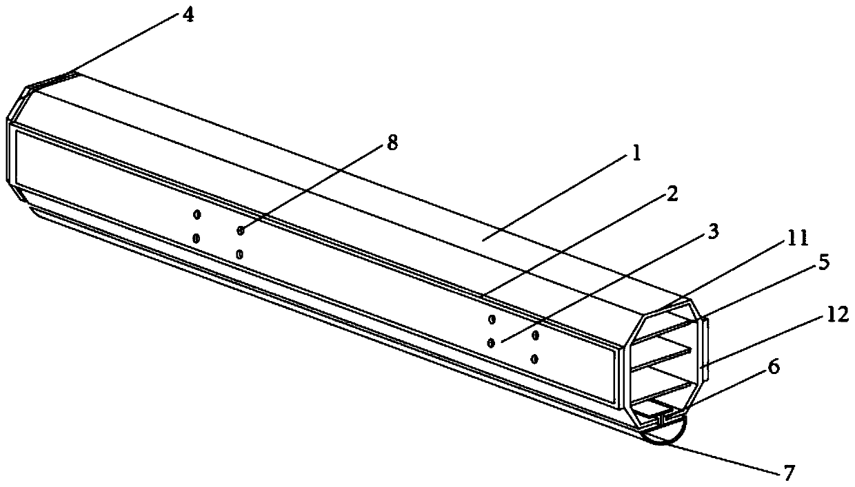
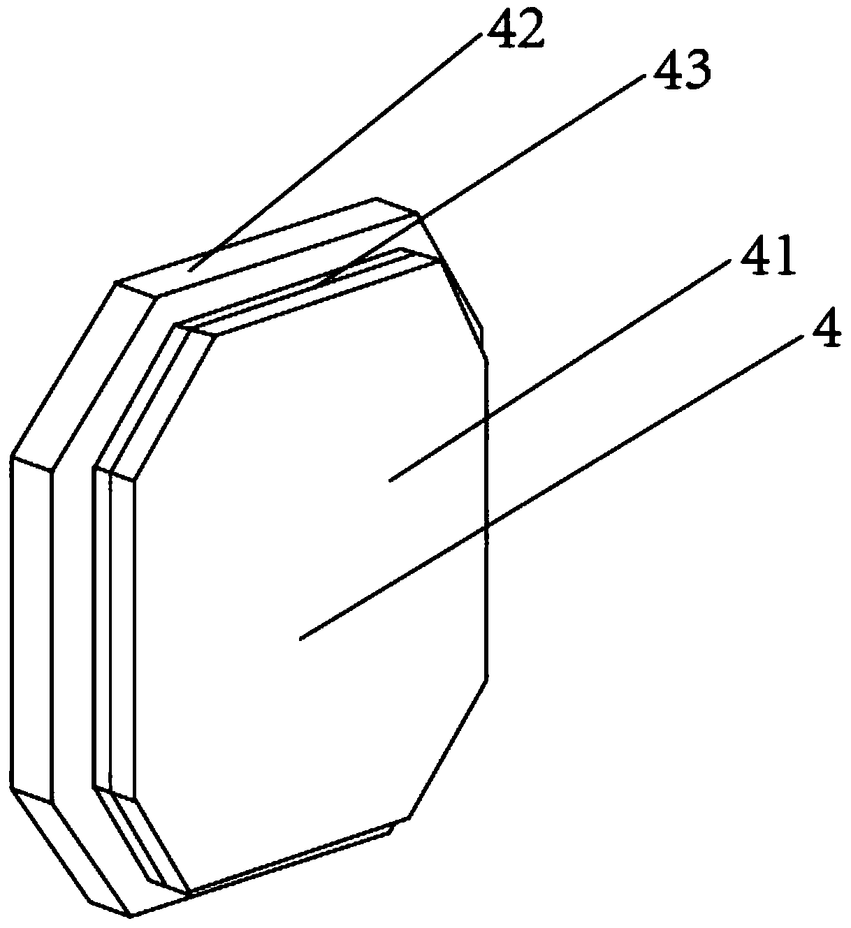
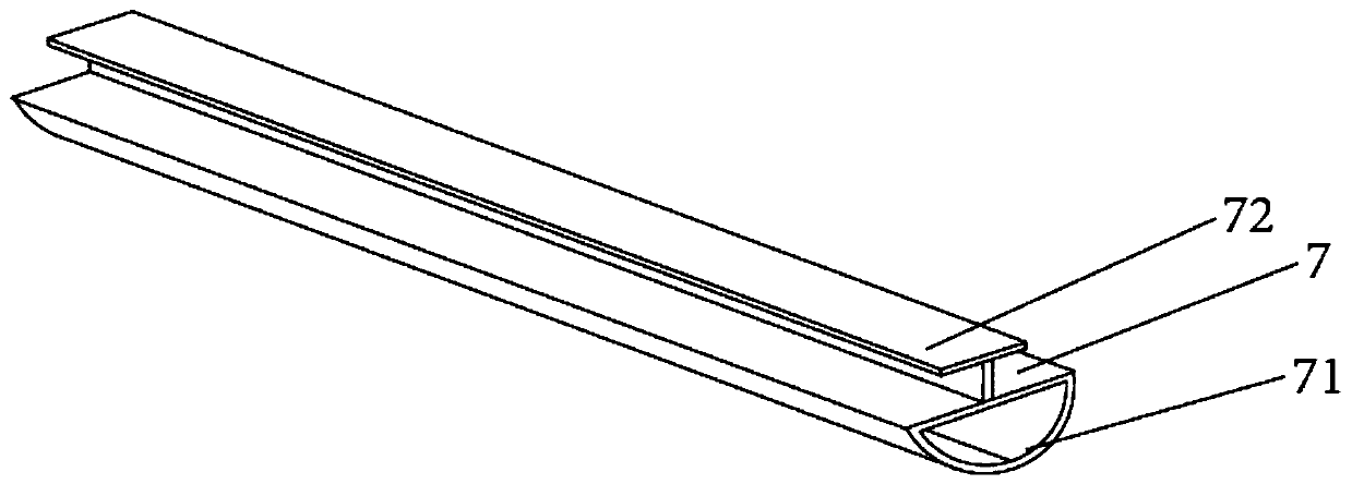
The invention discloses a vehicle barrier rod device based on security and defense engineering. The device comprises a vehicle barrier rod body, packaging covers connected to the two ends of the vehicle barrier rod body, and buffer plates arranged on the two sides of the vehicle barrier rod body. The buffer plates are arranged on the outer sides of vertical rods, so that a buffer effect is achieved on the vehicle barrier rod body, and the service time of the vehicle barrier rod body is prolonged; reflective stickers are attached to the outer sides of the buffer plates, so that a driver can observe the position of the vehicle barrier rod conveniently; mounting holes are arranged in the vehicle barrier rod body, so that people can install placards or signs with parking patterns conveniently;a reinforcing plate is installed at a joint of each connecting plate and the corresponding vertical plate, so that a role of supporting and reinforcing can be exerted; the packaging covers are arranged to package the two ends of the vehicle barrier rod, and a sealing ring is arranged on the outer side edge of an inserting plate, so that the sealing performance of connecting the packaging covers and the vehicle barrier rod body is improved, and a situation that the interior of the vehicle barrier rod body is corroded due to the fact that the rainwater sinks into the vehicle barrier rod body isavoided; and furthermore, an anti-collision strip is arranged, so that the bottom of the vehicle barrier rod body is protected, and the damage degree of the vehicle barrier rod body is reduced.

Description

technical field [0001] The invention relates to the technical field of traffic barriers, in particular to a traffic barrier device based on safety protection engineering. Background technique [0002] In the roads or entrances and exits of various public places such as residential areas, shopping malls, and schools, there are generally barriers to intercept vehicles. During the use of the barriers, a small number of vehicles will collide with the barriers. The length of the bar is long, if its thickness increases, it will increase the economic cost, so that when the bar collides with the vehicle, the bar may be deformed or the bar cannot be used, reducing its service life. The corner of the barrier bar has low compressive strength and is prone to deformation. The sealing of both ends of the barrier bar is not good, so that a small amount of rainwater will enter the inside of the barrier bar, which will cause corrosion inside. Painting or using other processes to prevent rai...

Claims


Application Information

Patent Timeline
Patent Type & Authority Applications(China)
IPC IPC(8): E01F13/04E01F9/619E01F9/669
CPCE01F13/04E01F9/619E01F9/669
Inventor 范桂侠
Owner 合肥森弗卡电子科技有限公司
Why Eureka
Try Eureka