
Roof beam reinforcing mechanism

A technology for roof beams and reinforcement components, which is applied in building construction, building maintenance, construction, etc., can solve problems such as good stability of roof beam reinforcement mechanisms, and achieve the effect of good stability, good effect, and avoidance of shaking.

Pending Publication Date: 2020-02-28
CHINA THIRD METALLURGICAL GRP
View PDF0 Cites 1 Cited by
  • Summary
  • Abstract
  • Description
  • Claims
  • Application Information

AI Technical Summary

Problems solved by technology

[0004] The purpose of the present invention is to provide a roof beam reinforcement mechanism, which has the advantages of good stabilizing effect and solves the problem of good stabilization effect of the existing roof beam reinforcement mechanism

Method used


Image

  • Roof beam reinforcing mechanism
  • Roof beam reinforcing mechanism
  • Roof beam reinforcing mechanism

Examples


Embodiment Construction

[0019] In order to enable those skilled in the art to better understand the technical solution of the present invention, the present invention will be described in detail below in conjunction with the accompanying drawings. The description in this part is only exemplary and explanatory, and should not have any limiting effect on the protection scope of the present invention. .

[0020] It should be noted that like numerals and letters denote similar items in the following figures, therefore, once an item is defined in one figure, it does not require further definition and explanation in subsequent figures.

[0021] It should be noted that the orientation or positional relationship indicated by the terms "center", "upper", "lower", "left", "right", "vertical", "horizontal", "inner" and "outer" are Based on the orientation or positional relationship shown in the drawings, or the orientation or positional relationship that the inventive product is usually placed in use, it is onl...


PUM


Abstract

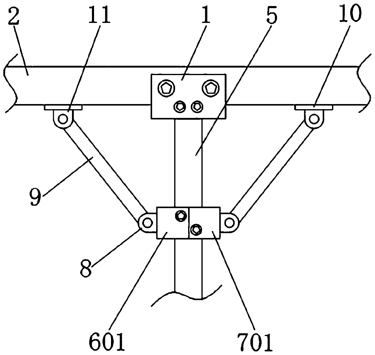
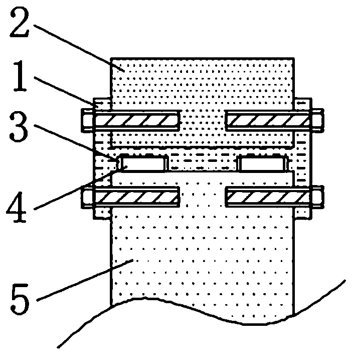
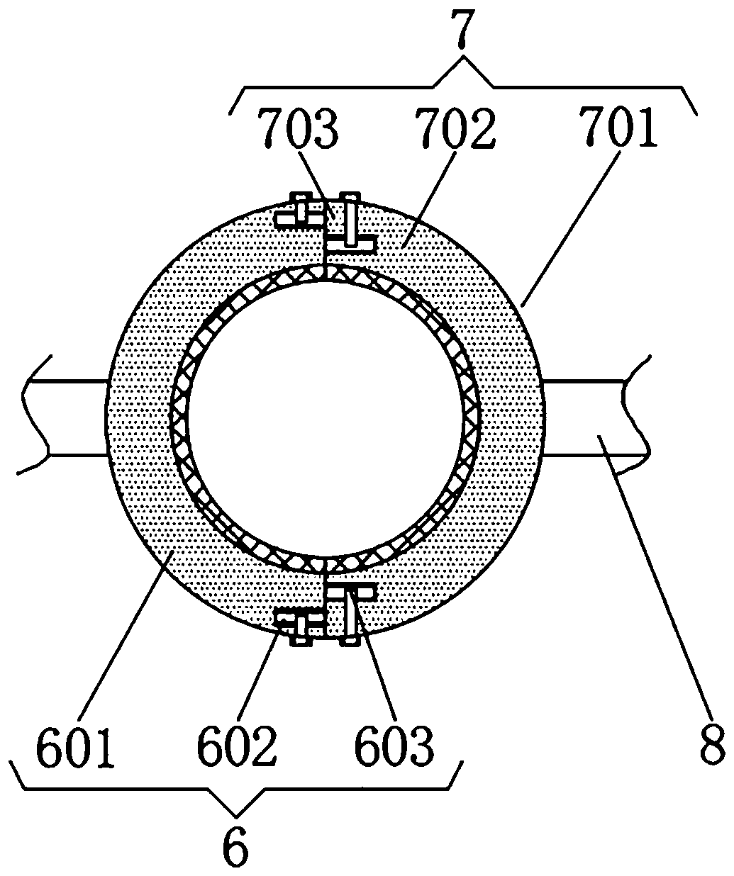
The invention discloses a roof beam reinforcing mechanism. The roof beam reinforcing mechanism comprises an I-shaped beam, and a main beam is arranged at the top of the I-shaped beam. Positioning grooves are formed in the two sides of the bottom of the I-shaped beam. Positioning blocks are arranged at the tops of inner cavities of the positioning grooves. The bottoms of the positioning blocks arefixedly connected with supporting rods, and reinforcing assemblies are arranged on the left sides of the supporting rods. According to the roof beam reinforcing mechanism, by means of the mutual cooperation of the I-shaped beam, the main beam, the positioning grooves, the positioning blocks, the supporting rods, the reinforcing assemblies, an auxiliary assembly, a first movable block, a reinforcing rod, a supporting block and a second movable block, the advantage of being good in stabilizing effect is achieved, and the problem that an existing roof beam reinforcing mechanism is poor in stabilizing effect is solved; reduction of the roof beam stabilizing performance is avoided, collapse of a roof beam after long-time use is avoided, and safety accidents are avoided; and a fixing mechanism is simple in structure and convenient to assemble, time and labor are saved, the work intensity is reduced, and the needs of a user can be met.

Description

technical field [0001] The invention relates to the technical field of buildings, in particular to a roof beam reinforcement mechanism. Background technique [0002] Roof beam refers to the main structural member that bears the pressure from purlins and roof panels in the roof structure. It mainly bears bending moment and shear force. Roof beams are classified into wooden beams, which occupy a large seat in modern buildings. T-shaped beams, thin-web beams, roof trusses, rectangular beams and T-shaped beams are suitable for cast-in-place reinforced concrete structures. Thin-web beams and roof trusses are prefabricated on site or by prefabricated manufacturers, and are hoisted by machinery. Reinforced concrete beams are prefabricated. Stressed and non-prestressed, steel frame beams, steel frame structures are more common in factory buildings and large-span building structures, and the roof truss structure is assembled by welding and bolting steel rods. [0003] At present, th...

Claims


Application Information

Patent Timeline
Patent Type & Authority Applications(China)
IPC IPC(8): E04G23/02E04G23/04
CPCE04G23/0218E04G23/04
Inventor 张浩赵淼毕重生刘婷婷
Owner CHINA THIRD METALLURGICAL GRP
Learn More