Indoor unit of air conditioner

An air conditioner indoor unit and body technology, applied in the field of air conditioners, can solve problems affecting user experience, indoor temperature effects, indoor temperature fluctuations, etc.

Inactive Publication Date: 2020-02-28
HISENSE (SHANDONG) AIR CONDITIONING CO LTD
View PDF7 Cites 6 Cited by
  • Summary
  • Abstract
  • Description
  • Claims
  • Application Information

AI Technical Summary

Problems solved by technology

[0002] On-hook fresh air devices are mostly installed on the side of the indoor unit of the air conditioner, and the outdoor fresh air is introduced into the room through the fresh air pipe. Since there is no total heat exchanger in the fresh air system and does not pass...

Method used


Image

  • Indoor unit of air conditioner
  • Indoor unit of air conditioner
  • Indoor unit of air conditioner

Examples


Embodiment 1

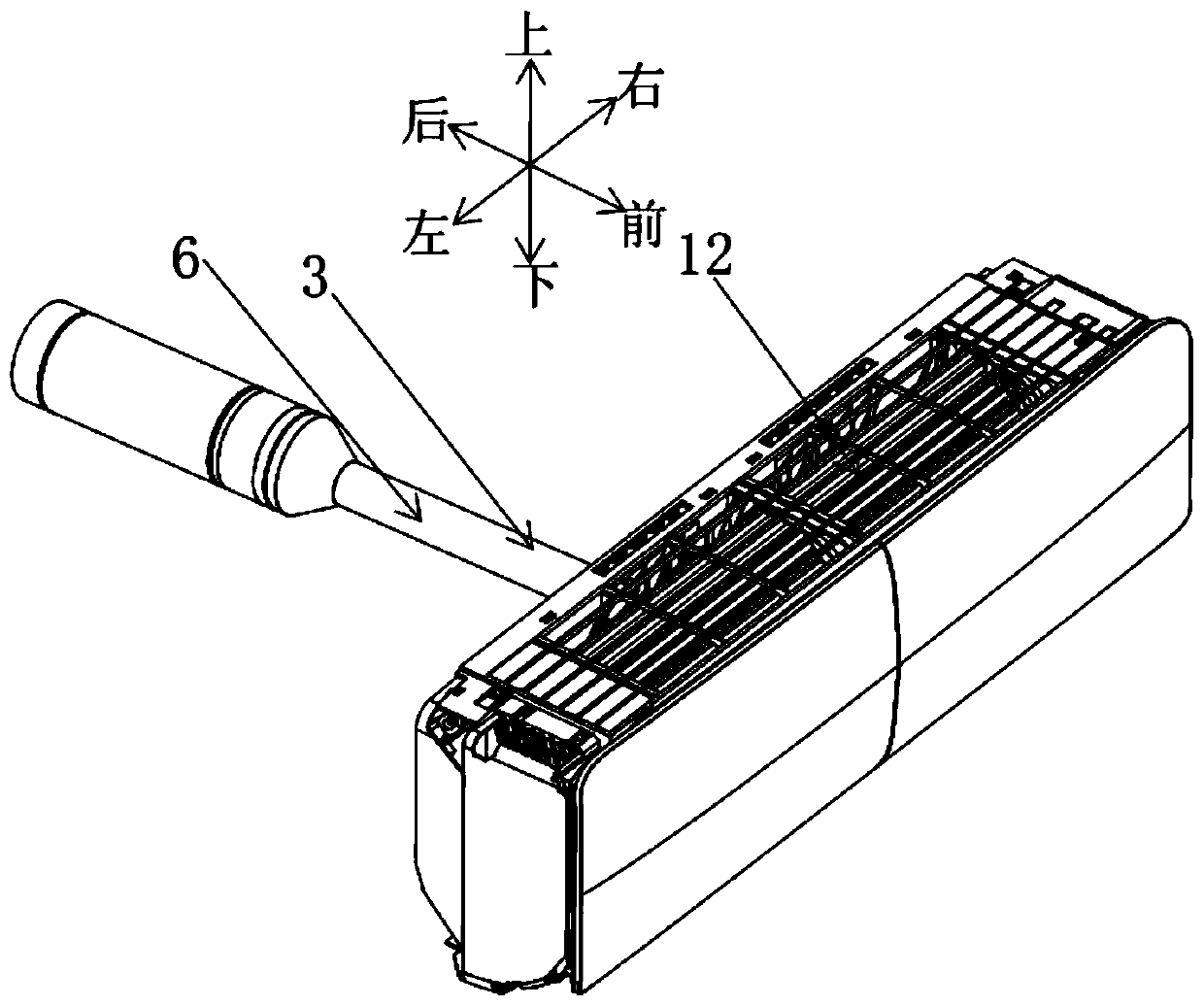
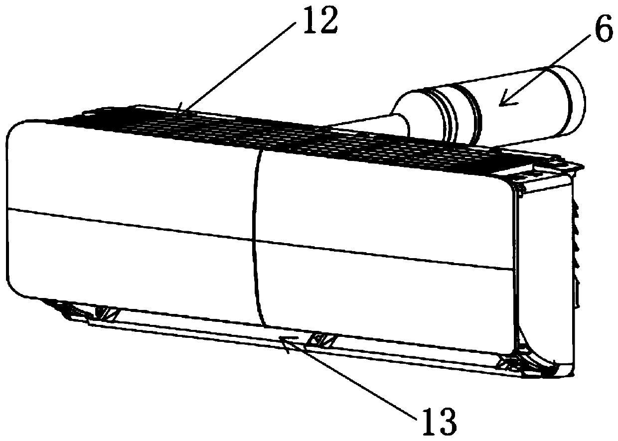
[0046] Such as Figure 1-Figure 11 As shown, an air conditioner indoor unit includes a body, and the body includes a base 1 and a housing combined with the base 1 . Such as Figure 1-Figure 2 As shown, the top of the air-conditioning indoor unit is provided with an air inlet 12, and the front and lower side of the air-conditioning indoor unit is provided with an air outlet 13.

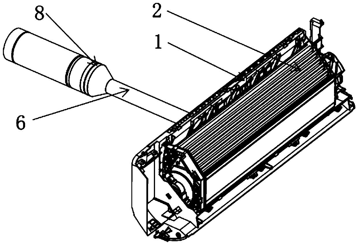
[0047] Such as Figure 3-Figure 7 As shown, the left mounting bracket 21 is installed on the left end of the evaporator 2, and the right mounting bracket 22 is installed on the right end; the left mounting bracket 21 and the right mounting bracket 22 are fixed on the base 1 to fix the evaporator 2. The evaporator 2 cooperates with the base 1 to form an accommodating chamber for the main cross-flow fan 51 , the rotation axis of the main cross-flow fan 51 is parallel to the extension direction of the air outlet 13 on the lower front side of the air conditioner indoor unit.

[0048] The air-conditionin...

Embodiment 2

[0069] The principle of the second embodiment is the same as that of the first embodiment, the main difference is that: Figure 12-Figure 13 As shown, the indoor unit of the air conditioner is provided with a purification module 4 at one end; the fresh air duct 31 is connected in series with the purification duct 41 of the purification module 4 .

[0070] In this embodiment, the purification module 4 is arranged in the casing of the air conditioner indoor unit.

[0071] The air-conditioning indoor unit is located adjacent to the main air duct 5 and is provided with a purification air duct 41, and the purification air duct 41 is arranged side by side with the main air duct 5; wherein, the purification air duct 41 communicates with the air inlet 12 and the air outlet 13 ; that is, the purification air duct 41 shares the air inlet 12 and the air outlet 13 with the main air duct 5 . The purification air duct 41 is provided with a purification cross-flow fan 42, and the main cross...


PUM


Abstract

The invention provides an indoor unit of an air conditioner. A fresh air duct is connected with a main air duct and/or a purification air duct of the air conditioner indoor unit in series, wherein a fresh air module of an in-pipe fresh air fan is arranged in a fresh air pipe; and the adjacent distance between every two adjacent in-pipe fresh air fans is limited. According to the arrangement structure, when at least an air conditioner mode and a fresh air mode operate at the same time, the temperature of fresh air introduced into a room from the fresh air pipe is adjusted; on one hand, the temperature adjusting effect on the fresh air can be improved; on the other hand, the main air duct or the purification air duct can be effectively utilized for increasing the fresh air volume; in addition, due to the arrangement of the adjacent distance between every two adjacent in-pipe fresh air fans, turbo-charging airflow can be formed between every two adjacent in-pipe fresh air fans, the freshair volume introduced from the outside is remarkably increased, indoor fresh air noise is effectively controlled, and the noise value is obviously reduced; and furthermore, the in-pipe fresh air fansare arranged in the fresh air duct, the space of the air conditioner indoor unit does not need to be increased, and the overall performance of the air conditioner indoor unit is improved.

Description

technical field [0001] The invention belongs to the technical field of air conditioners, and in particular relates to an air conditioner indoor unit. Background technique [0002] On-hook fresh air devices are mostly installed on the side of the indoor unit of the air conditioner, and the outdoor fresh air is introduced into the room through the fresh air pipe. Since there is no total heat exchanger in the fresh air system and does not pass through the evaporator, when the temperature difference between indoor and outdoor is large, the outdoor fresh air Fresh air will have a greater impact on the indoor temperature, resulting in greater fluctuations in the indoor temperature, seriously affecting the user experience. [0003] In view of this, the present invention is proposed. Contents of the invention [0004] The present invention aims at the above technical problems and proposes an air conditioner indoor unit. [0005] In order to achieve the above object, the technica...

Claims


Application Information

Patent Timeline
IPC IPC(8): F24F1/0011F24F1/0025F24F1/0073F24F13/02F24F13/24F24F13/28F24F13/30
CPCF24F1/0011F24F1/0025F24F1/0073F24F13/02F24F13/24F24F13/28F24F13/30
Inventor 肖美娜周瑜
Owner HISENSE (SHANDONG) AIR CONDITIONING CO LTD
Why Eureka
Try Eureka