Method for measuring vehicle speed based on fuzzy image
A fuzzy image and vehicle speed technology, applied in image analysis, image data processing, devices using optical methods, etc., can solve the problems of inconvenient installation of speed measuring equipment, complicated installation, and complicated measurement process, and achieve simple and fast measurement and calculation of vehicle speed. The effect of fewer cameras and fewer parameters required
- Summary
- Abstract
- Description
- Claims
- Application Information
AI Technical Summary
Problems solved by technology
Method used
Image
Examples
Embodiment 1
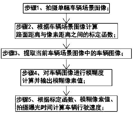
[0037] A kind of method of measuring vehicle speed based on fuzzy image of the present embodiment, such as figure 1 As shown, a method for measuring vehicle speed based on fuzzy images includes the following steps:
[0038] Step 1. Shooting a single vehicle scene image in real time;
[0039] Step 2, calculating the calibration function between the road surface distance and the pixel distance according to the vehicle scene image;
[0040] Step 3, extracting the vehicle image in the current vehicle scene image;
[0041] Step 4. Carry out fuzziness calculation on the vehicle image and output the fuzzy pixel value;
[0042] Step 5. Calculate the driving speed of the vehicle according to the calibration function, the blurred pixel value, and the shooting exposure time.
[0043] The camera is used to capture the scene image of the vehicle, and the lens of the camera is installed facing the driveway to ensure that the lens of the camera can completely capture the license plate of ...
Embodiment 2
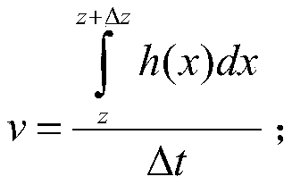
[0048] This embodiment is further optimized on the basis of Embodiment 1, and the following formula is used to calculate the vehicle speed:
[0049]
[0050] Where: v is the speed of the vehicle;
[0051] h(x) is a calibration function;
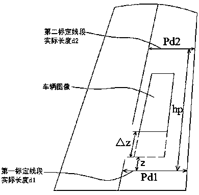
[0052] z is the minimum pixel distance between the vehicle image and the first calibration line segment;
[0053] △z is the fuzzy pixel value;
[0054] Δt is the shooting exposure time.
[0055] The sub-steps of calculating the calibration function in step 2 are as follows:
[0056] Step 2.1, if figure 2 As shown, two first calibration line segments and second calibration line segments that are perpendicular to the length direction of the road surface and parallel to each other are respectively selected in the vehicle scene image, and the actual lengths of the first calibration line segment and the second calibration line segment are measured as d 1 and d 2 ;
[0057] Step 2.2, calculate the pixel lengths of the first calibration l...
Embodiment 3
[0066] This embodiment is further optimized on the basis of the above-mentioned embodiment 1 or 2. In the step 1, a high-speed camera is used to shoot the vehicle image, and several groups of fixed shutter exposure times are set, and the fixed shutter exposure time is adjusted according to the ambient light intensity. .
[0067] In order to ensure the clarity of the captured vehicle scene images as much as possible, a high-speed camera is selected to capture vehicle images, which can capture high-speed vehicles in time. At the same time, several groups of fixed shutter exposure times are set according to the ambient light intensity. When the ambient light intensity is weak, the corresponding fixed shutter exposure time is longer; when the ambient light intensity is strong, the corresponding fixed shutter exposure time is shorter.
[0068] Other parts of this embodiment are the same as those of Embodiment 1 or 2 above, so details are not repeated here.
PUM
 Abstract
Description
Claims
Application Information
 - R&D
- Intellectual Property
- Life Sciences
- Materials
- Tech Scout
- Unparalleled Data Quality
- Higher Quality Content
- 60% Fewer Hallucinations
Browse by: Latest US Patents, China's latest patents, Technical Efficacy Thesaurus, Application Domain, Technology Topic, Popular Technical Reports.
© 2025 PatSnap. All rights reserved.Legal|Privacy policy|Modern Slavery Act Transparency Statement|Sitemap|About US| Contact US: help@patsnap.com


