Ultra-wide-angle camera lens

A camera lens and ultra-wide-angle technology, applied in the field of optical systems, can solve problems that cannot meet the needs of the electronic market, and achieve the effect of a large image circle

Pending Publication Date: 2020-02-28
辽宁中蓝光电科技有限公司
View PDF0 Cites 5 Cited by
  • Summary
  • Abstract
  • Description
  • Claims
  • Application Information

AI Technical Summary

Problems solved by technology

[0003] At present, the field of view of mainstream lenses on the market is generally between 70° and 80°, which can no longer meet the needs of the electronic market. There is an urgent need to design a mobile phone lens with a larger field of view to achieve ultra-large field of view shooting

Method used


Image

  • Ultra-wide-angle camera lens
  • Ultra-wide-angle camera lens
  • Ultra-wide-angle camera lens

Examples


Embodiment 1

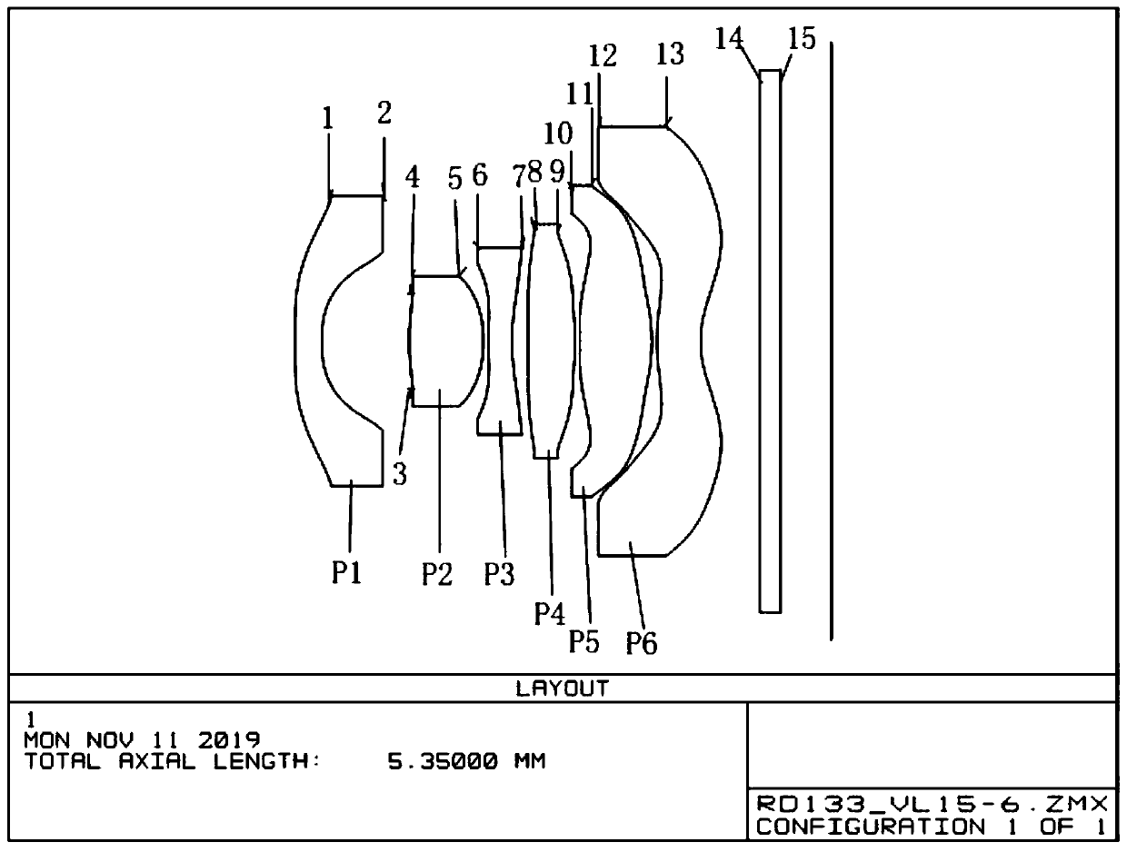
[0066] Such as figure 1 As shown, the ultra-wide-angle camera lens includes sequentially from the object side to the image side along the optical axis: a first lens P1 with negative refractive power, and the object side and the image side are concave surfaces; with positive refractive power, the object side and the image side Both are convex second lenses P2; have negative refractive power, the object side is convex and the third lens P3 is concave as the side; have positive refractive power, the object side is concave and the fourth lens P4 is convex as the side; Positive refractive power, the object side is concave and the fifth lens P5 is convex as the side; has negative refractive power, the object side is convex and the sixth lens P6 is concave as the side; between the first lens and the second lens With aperture. It also satisfies the following conditions:

[0067] 0.75<(R1+R2) / (R1-R2)<0.82

[0068] -0.36

[0069] 0.15

[0070] -1.5

Embodiment 2

[0095] In this embodiment, the FOV (1.0F) of the lens is 167.5°, the aperture value is Fno 2.28, the effective focal length efl of the optical system is 1.6045mm, the half-image height IH is 2.934mm, the optical TTL is 5.35mm, and the optical back focus BFL is 1.1mm. The specific design parameters of the lens with an image circle of 6.168mm are shown in Table 2(a), Table 2(b), and Table 2(c).

[0096] Table 2(a)

[0097]

[0098]

[0099] Table 2(b)

[0100]

[0101]

[0102] Table 2(c)

[0103] (R1+R2) / (R1-R2) 0.8172 f2 / f3 -0.3514 BFL / TTL 0.2056 f1 / f -1.3997 (R8+R9) / (R8-R9) 1.0109 IH / TTL 0.5484 Sd s6 / IH 0.7107 f5 / f6 -0.8042 f3 / TTL -0.9542 f2 / CT2 2.4315

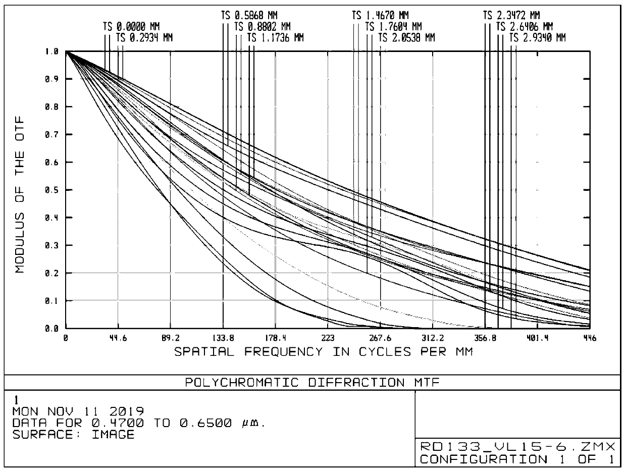
[0104] see Figure 7 , the MTF transfer function curve of Example 2 has a higher resolving power at the 1 / 4 frequency central field of view MTF greater than 0.76.

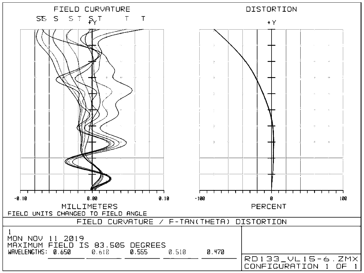
[0105] see Figure 8 , the field curvature & distortion curve of Example 2, ...

Embodiment 3

[0109] In this embodiment, the FOV (1.0F) of the lens is 167.1°, the aperture value is Fno 2.35, the effective focal length efl(f) of the optical system is 1.6626mm, the half-image height IH is 2.934mm, the optical TTL is 5.35mm, and the optical back focus is BFL The specific design parameters of the 1.1mm lens with an image circle of 6.168mm are shown in Table 3(a), Table 3(b), and Table 3(c).

[0110] Table 3(a)

[0111]

[0112] Table 3(b)

[0113]

[0114]

[0115] Table 3(c)

[0116] (R1+R2) / (R1-R2) 0.8064 f2 / f3 -0.354 BFL / TTL 0.2056 f1 / f -1.452 (R8+R9) / (R8-R9) 1.1359 IH / TTL 0.5484 Sd s6 / IH 0.7229 f5 / f6 -1.468 f3 / TTL -0.9026 f2 / CT2 2.3986

[0117] see Figure 12 , the MTF transfer function curve of Example 3 has a higher resolving power at the 1 / 4 frequency central field of view MTF greater than 0.77.

[0118] see Figure 13, the field curvature & distortion curve of Example 3, under the la...


PUM

PropertyMeasurementUnit
optical path lengthaaaaaaaaaa

Abstract

The invention relates to an ultra-wide-angle camera lens which comprises a first lens , a second lens, a third lens, a fourth lens, a fifth lens and a sixth lens sequentially from an object side to animage side along optical axis. The first lens has negative refraction force, and each of the object side face and the image side face is a concave face; the second lens has positive refraction force,and each of the object side face and the image side face is a convex face; the third lens has negative refraction force, the object side face is a convex face, and the image side face is a concave face; the fourth lens has positive refraction force, the object side face is a concave face, and the image side face is a convex face; the fifth lens has positive refraction force, the object side faceis a concave face, and the image side face is a convex face; the sixth lens has negative refraction force, the object side face is a convex face, and the image side face is a concave face; a diaphragmis arranged between the first lens and the second lens. The ultra-wide-angle camera lens can meet large-wide-angle and large-field-angle needs while imaging quality is ensured.

Description

technical field [0001] The invention relates to an optical system, in particular to an ultra-wide-angle camera lens suitable for smart phones or ultra-thin video camera devices. Background technique [0002] With the continuous innovation of smartphone camera functions and shooting modes, people's demand for mobile phone camera shooting functions is not limited to high resolution and large aperture, but is developing towards a more novel direction-wide-angle end. Therefore, in addition to high requirements for high resolution, large aperture and ultra-thin features in the electronics market, a large field of view is also a development direction worthy of attention. [0003] At present, the field of view of mainstream lenses on the market is generally between 70° and 80°, which can no longer meet the needs of the electronic market. There is an urgent need to design a mobile phone lens with a larger field of view to achieve ultra-large field of view shooting. Contents of the...

Claims


Application Information

Patent Timeline
Patent Type & Authority Applications(China)
IPC IPC(8): G02B13/00G02B13/18G02B13/06G02B1/04
CPCG02B1/041G02B13/0045G02B13/06
Inventor 宋亮陈军
Owner 辽宁中蓝光电科技有限公司
Why Eureka
Try Eureka