A network method for object detection based on camera projection model

An item detection and model technology, applied in the field of network item detection, can solve problems such as increased deployment costs, large amount of calculation, and failure to achieve network performance well

Active Publication Date: 2020-05-22
GOSUN GUARD SECURITY SERVICE TECH
View PDF4 Cites 0 Cited by
  • Summary
  • Abstract
  • Description
  • Claims
  • Application Information

AI Technical Summary

Problems solved by technology

However, these end-to-end (End to End) networks for recognition have many practical problems: First, these networks require a huge amount of calculations, making it impossible to actually land
The inability to implement includes two levels. One is that the huge amount of calculation leads to higher GPU usage, which increases the deployment cost. The second level is that the huge amount of calculation makes it difficult to achieve real-time calculation. In order to achieve real-time calculation, often need Deploying more computing equipment will cause waste of resources while increasing costs
Second, directly using the simplified network models of these classic networks cannot achieve the performance of the network very well.
Third, some networks with good performance do not design the network for the projection model of the camera, but prefer the network design based on the image itself. This design is more general, but not efficient.

Method used


Image

  • A network method for object detection based on camera projection model
  • A network method for object detection based on camera projection model
  • A network method for object detection based on camera projection model

Examples


Embodiment Construction

[0044] The present invention will be further described below in conjunction with the accompanying drawings and specific embodiments.

[0045] A method for designing an object detection network based on a camera projection model, comprising the following steps:

[0046] Step 1: Perform mathematical statistics on the data to be detected, confirm the minimum size and maximum size of the target to be detected on the image and the distribution of the target to be detected on the image, and design the relevant network input size accordingly. (The input size depends on the computing resources at that time. Generally, the larger the detection target, the smaller the network input size can be designed, and the smaller the detection target, the larger the network input size)

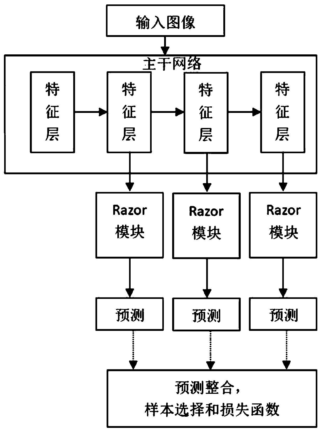
[0047] Step 2: According to the designed input size, calculate the proportional relationship between the minimum detection size and the input size, and determine the output layer of the network. Generally, the ne...


PUM


Abstract

The invention discloses an object detection network method based on a camera projection model, including: inputting an image, designing and calculating an anchor frame of the input image; backbone network: inputting the image into the backbone network, and outputting it after passing through multiple feature layers; designing a Razor module ; first encode the ground truth, and then predict; negative sample screening; training and selection of samples, design loss function, training, to obtain the training model; the use of the model; when the training is completed, use the obtained function parameters to deduce the model, The obtained estimate of each anchor box is obtained to obtain the probability of the existence of the target under the anchor box, and the real position in the actual image is obtained by inverse deduction. The article detection network method proposed by the present invention greatly reduces the amount of computation while still retaining the performance of accurate detection in the network. In autonomous driving and surveillance, two industries that rely heavily on camera projection models, it has proven its high efficiency and achieved very good results.

Description

technical field [0001] The present invention relates to the field of network object detection, and more specifically, to an object detection network method and system based on a camera projection model. Background technique [0002] Convolutional neural network (CNN), as a very popular carrier for image recognition and detection, has achieved great success. Based on this technology, many application networks have been derived, such as VGG, ResNet, DenseNet, Yolo and other OneStage networks. . However, these end-to-end (End to End) networks for recognition have many practical problems: First, these networks require a huge amount of computation, making it impossible to actually implement them. The inability to implement includes two levels. One is that the huge amount of calculation leads to higher GPU usage, which increases the deployment cost. The second level is that the huge amount of calculation makes it difficult to achieve real-time calculation. In order to achieve rea...

Claims


Application Information

Patent Timeline
Patent Type & Authority Patents(China)
IPC IPC(8): G06K9/00G06K9/32G06N3/08
CPCG06N3/084G06V40/10G06V20/58G06V10/25
Inventor 肖刚王逸飞
Owner GOSUN GUARD SECURITY SERVICE TECH
Why Eureka
Try Eureka