Locking device for adjusting radiation area of communication antenna

A radiation area and locking device technology, applied in the direction of antenna support/installation device, antenna, electrical components, etc., can solve problems such as damage, cauldron dumping, instability, etc., to facilitate locking adjustment, reduce friction, and facilitate fixing Effect

Active Publication Date: 2020-02-28
东土科技(宜昌)有限公司
View PDF9 Cites 0 Cited by
  • Summary
  • Abstract
  • Description
  • Claims
  • Application Information

AI Technical Summary

Problems solved by technology

[0002] The antenna is a kind of converter, which transforms the guided wave propagating on the transmission line into electromagnetic waves propagating in the unbounded medium, or performs the opposite transformation. Generally, the antenna is reversible, that is, the same antenna can be used as a transmitting antenna , can also be used as a receiving antenna. The basic characteristic parameters of the same antenna as transmitting or receiving are the same. When using the antenna, it is necessary to lock the radiation area of ​​the antenna. When locking the radiation area of ​​the antenna, it is By rotating the antenna, the angle is changed, so that the radiation area of ​​the antenna can be locked. However, in the prior art, the existing antenna often sees a cauldron. When the existing antenna rotates the cauldron , due to the large volume of the cauldron, it is not easy to rotate it. At the same time, when the existing cauldron is in use, it can only rotate the whole cauldron, and cannot rotate the angle of the cauldron. It is inconvenient to lock the radiation area. At the same time, some existing cauldrons are placed directly on the ground, which is extremely unstable, and it is easy to cause the cauldron to fall over, thereby causing damage and affecting the use of the cauldron. Some communication pots are placed outside, which can easily affect the model of the communication pot due to rainy weather. At the same time, due to the erosion of rainwater, in long-term use, it is very easy to cause the communication pot to rust, and then it will be greatly reduced. The service life of the communication pot

Method used


Image

  • Locking device for adjusting radiation area of communication antenna
  • Locking device for adjusting radiation area of communication antenna
  • Locking device for adjusting radiation area of communication antenna

Examples


Embodiment 1

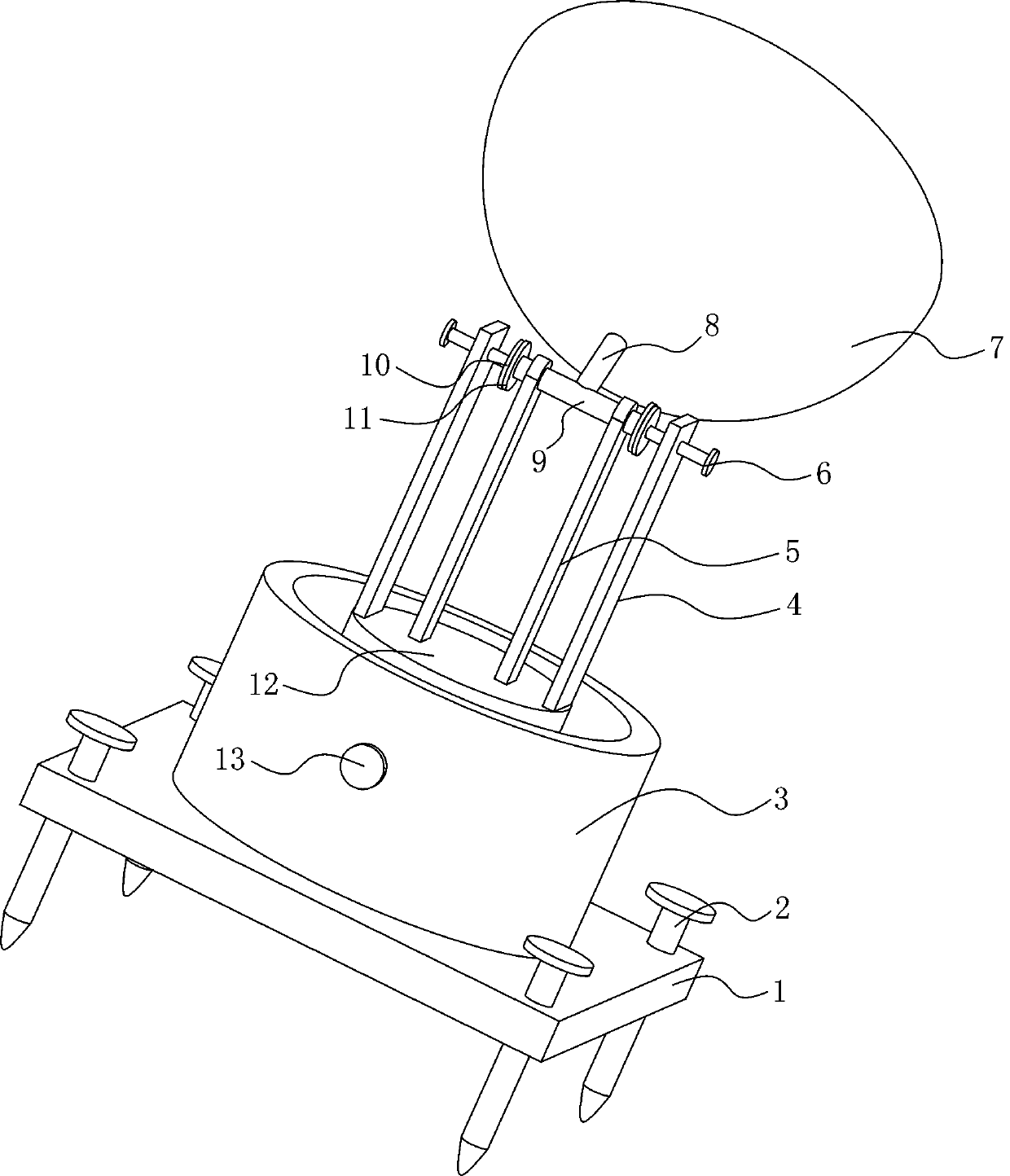
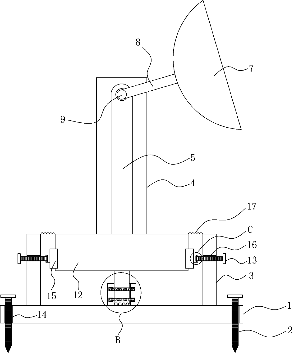
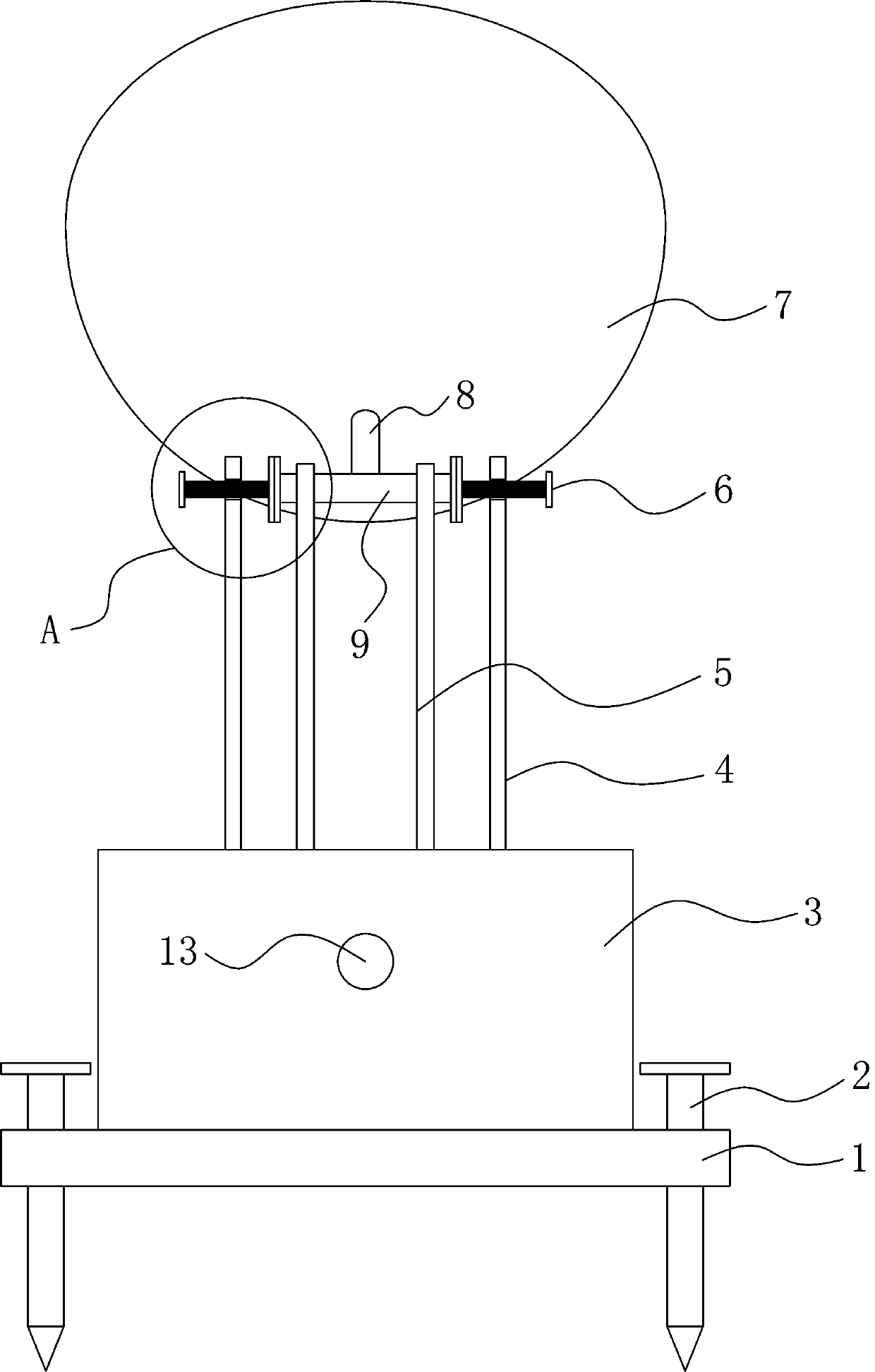
[0031] The preferred solution is as Figure 1 to Figure 6 As shown, a locking device for adjusting the radiation area of ​​a communication antenna includes a bottom plate 1, the top of the bottom plate 1 is provided with first threaded holes 14 near the four corners, and the inner surface walls of the first threaded holes 14 are threaded There is a first screw mandrel 2, and both ends of the first screw mandrel 2 extend to the outside of the first threaded hole 14, and the bottom end of the first screw mandrel 2 is a pointed structure, by rotating the first screw mandrel 2, Therefore, the first threaded mandrel 2 moves down inside the first threaded hole 14, so that the first threaded mandrel 2 can go deep into the ground, so that the position of the whole device can be better fixed in use.

[0032] The top of the bottom plate 1 is welded with a circular frame 3, which can better fix the position of the hollow cylinder 19. The inner bottom surface of the circular frame 3 is we...

Embodiment 2

[0036] On the basis of embodiment 1, introduce as follows with more optimal technical scheme:

[0037] The preferred solution is as Figure 1 to Figure 4 As shown, the outer surface of the round block 12 is adhered with an elastic sealing layer 17 near the top edge, and one side of the elastic sealing layer 17 is adhered to the inner surface wall of the ring frame 3 near the top edge, and the elastic sealing layer 17 can be Stretching and deformation facilitate the rotation of the round block 12. At the same time, the elastic sealing layer 17 can better prevent impurities from entering the inside of the ring frame 3. The top of the round block 12 is welded with fixed strips 4 near the edges of both sides. The fixed strip 4 can better fix the position of the third screw mandrel 6. There are two fixed strips 4, and a third side surface near the top edge of the two fixed strips 4 is provided. Threaded hole 18, the inner surface wall of the 3rd threaded hole 18 is threadedly conn...

Embodiment 3

[0039] On the basis of embodiment 1 and embodiment 2, introduce as follows with more optimal technical scheme:

[0040] The preferred solution is as Figure 7 with Figure 8 As shown, the outer surface of the rotating rod 9 is welded with a short rod 8, the top of the short rod 8 is welded with a communication pot 7, a waveguide 705 is arranged at the center of the inner wall of the communication pot 7, and an integrated circuit is arranged inside the waveguide 705. plate, the top of the waveguide 705 is provided with a feed source 703, and the outer surface of the waveguide 705 is equidistantly fixed with three oblique support rods 701 along the circumferential direction, and the bottom ends of the three oblique support rods 701 are in contact with the inner surface wall of the communication pot 7 Fixed connection, the inclined support rod 701 can better fix the position of the waveguide 705, the inner surface wall of the communication pot 7 is equidistantly arranged with fo...


PUM


Abstract

A locking device for adjusting a radiation area of a communication antenna comprises a bottom plate. A circular ring frame is arranged on the bottom plate. A hollow cylinder is arranged on the inner bottom surface of the circular ring frame. Two first circular sliding grooves are formed in the inner surface wall of the hollow cylinder, and circular ring plates are embedded into the inner surface walls of the two first circular sliding grooves in a sliding mode. The number of the circular ring plates is two. A round rod is arranged between the inner surface walls of the two circular ring plates, and the top end of the round rod extends to the outer part of the hollow cylinder. A plurality of first sliding balls are embedded in a sliding manner in the bottom of the round rod at equal intervals, and the bottoms of the multiple first sliding balls are embedded in a sliding manner in the inner bottom face of the hollow cylinder. A plurality of second sliding balls are embedded in a slidingmanner in the outer surfaces of the two circular ring plates at equal intervals, and the outer surfaces of the multiple second sliding balls are embedded in a sliding manner in the inner surface wallsof the first circular sliding grooves. The direction of a communication pot can be rotated, the radiation area of the communication pot can be better locked in use, and the communication pot is convenient to use.

Description

technical field [0001] The invention belongs to the technical field of communication devices, in particular to a locking device for adjusting the radiation area of ​​a communication antenna. Background technique [0002] The antenna is a kind of converter, which transforms the guided wave propagating on the transmission line into electromagnetic waves propagating in the unbounded medium, or performs the opposite transformation. Generally, the antenna is reversible, that is, the same antenna can be used as a transmitting antenna , can also be used as a receiving antenna. The basic characteristic parameters of the same antenna as transmitting or receiving are the same. When using the antenna, it is necessary to lock the radiation area of ​​the antenna. When locking the radiation area of ​​the antenna, it is By rotating the antenna, the angle is changed, so that the radiation area of ​​the antenna can be locked. However, in the prior art, the existing antenna often sees a cauld...

Claims


Application Information

Patent Timeline
Patent Type & Authority Applications(China)
IPC IPC(8): H01Q1/12H01Q3/02H01Q15/16
CPCH01Q1/12H01Q3/02H01Q15/16
Inventor 刘勇龚国强丁晓波唐庭龙
Owner 东土科技(宜昌)有限公司
Why Eureka
Try Eureka