Mounting structure of motor

An installation structure and motor technology, applied in the field of motors, can solve the problems of power overflow, inability to meet the needs of multiple power outputs, waste, etc.

Inactive Publication Date: 2020-02-28
嘉兴新博信息科技有限公司
View PDF5 Cites 2 Cited by
  • Summary
  • Abstract
  • Description
  • Claims
  • Application Information

AI Technical Summary

Problems solved by technology

[0004] The existing motor fixing device can only fix the motor on the base so that it can be connected to different transmission shafts of the equipment. Some transmission shafts that require large power output need to be connected to a larger power motor, while small transmission shafts It is necessary to connect a low-power motor, and at the same time, even if it is the same drive shaft, the power requirements are different in different periods. In this case, multiple motors cannot meet the needs of various power outputs, and will also cause power overflow. cause unnecessary waste

Method used


Image

  • Mounting structure of motor
  • Mounting structure of motor
  • Mounting structure of motor

Examples


Embodiment Construction

[0029] In order to make the technical means, creative features, goals and effects achieved by the present invention easy to understand, the present invention will be further described below in conjunction with specific embodiments.

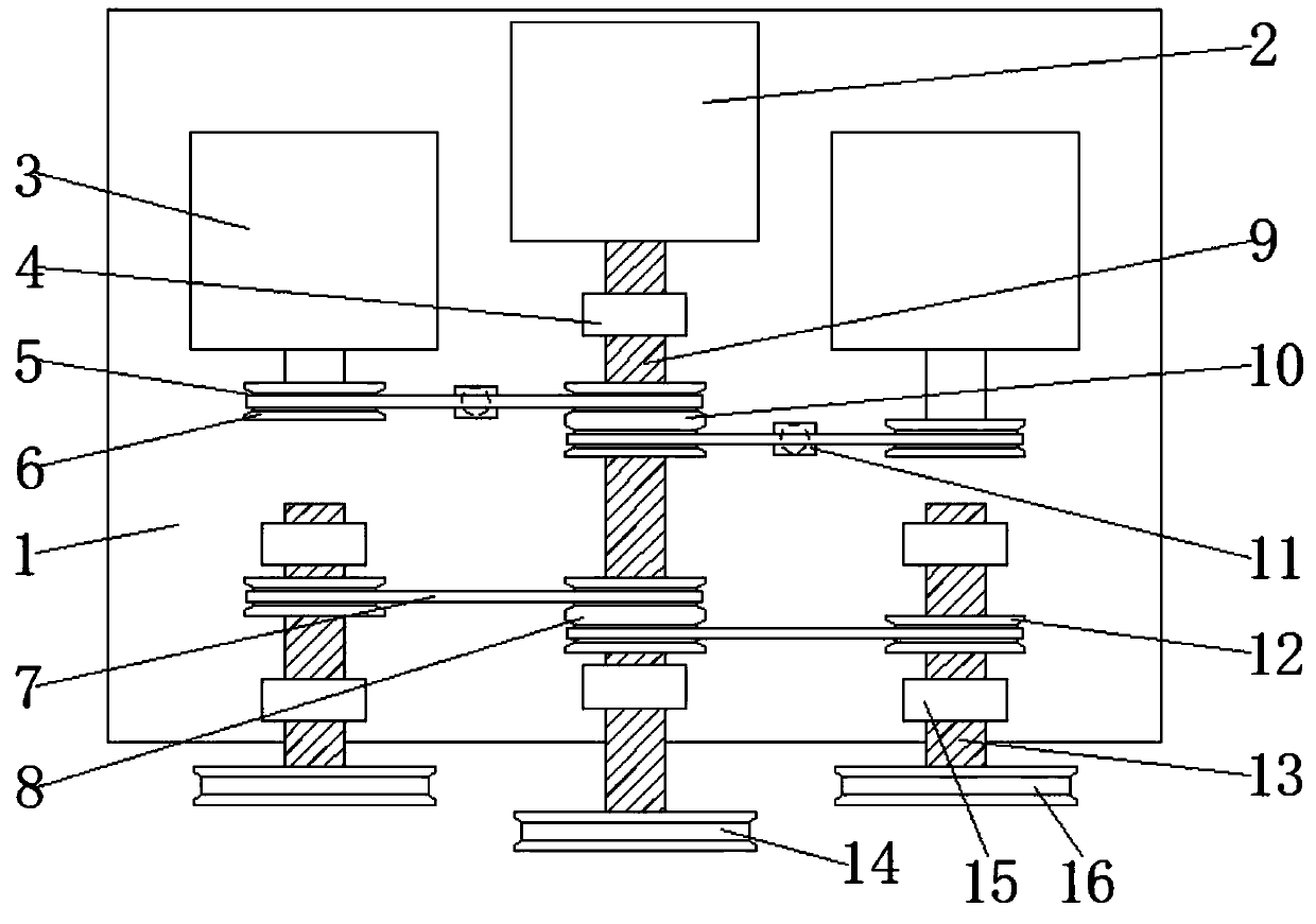
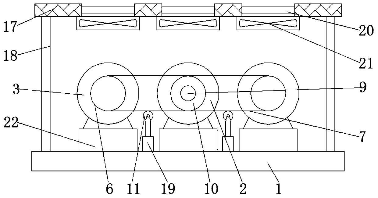
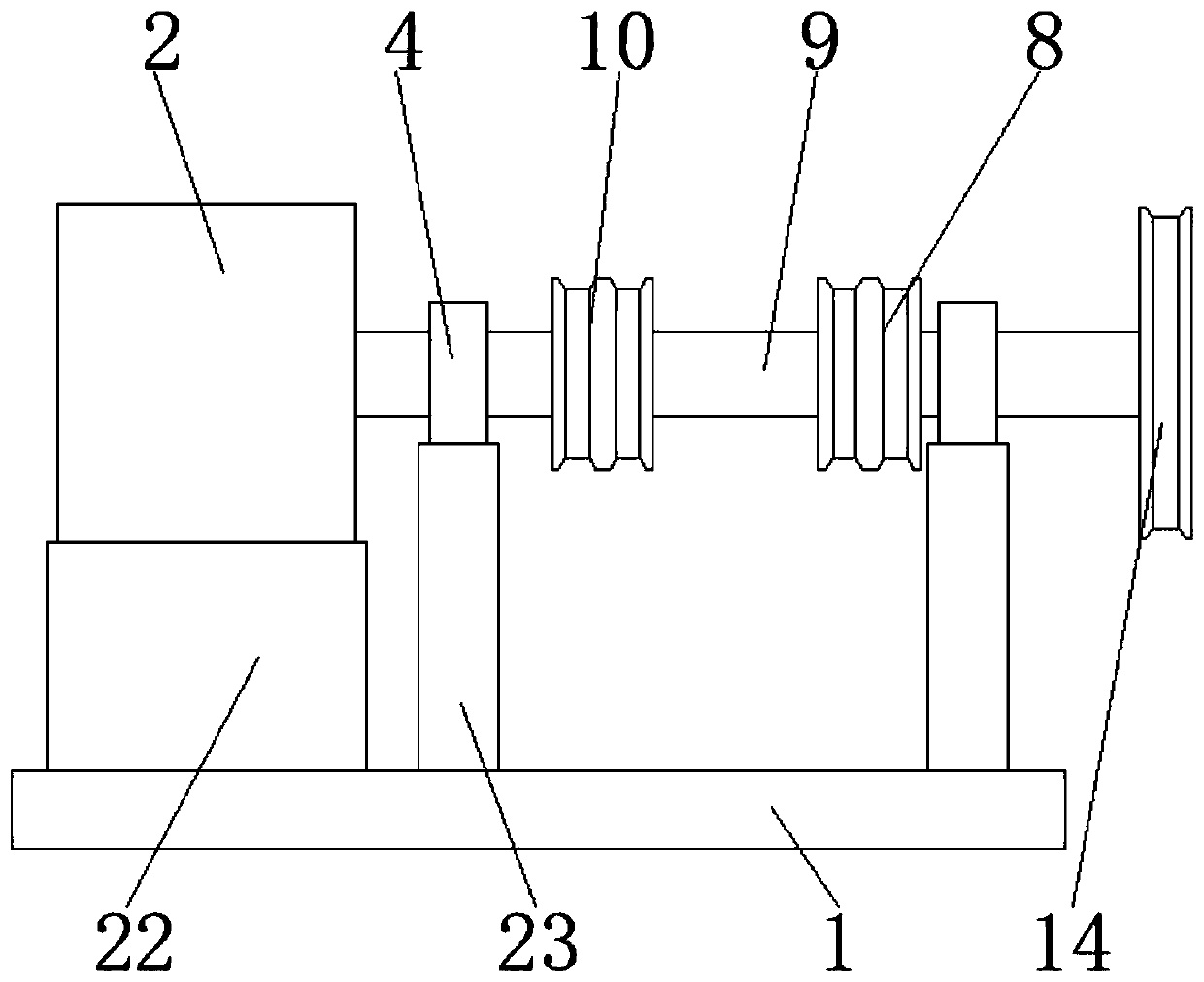
[0030] see Figure 1-5 , the present invention provides a technical solution: a motor installation structure, including a base 1 and a main motor 2, the main motor 2 is fixed on the support base 22 at the rear upper end of the base 1, the two sides of the main motor 2 The base 1 is supported and fixed with an auxiliary motor 3 by a support base 22, and the auxiliary motor 3 is two, and the bottoms of the main motor 2 and the auxiliary motor 3 are all fixed on the upper end of the fixing plate 24, and the fixing plate 24 is fixed by a bolt 25 Installed on the upper end of the support base 22, the upper end of the base 1 is provided with a rotating device and a transmission device;

[0031] The rotating device comprises a first transmission rod 9, ...


PUM


Abstract

The invention discloses a mounting structure of a motor. The mounting structure comprises a base and a main motor. The main motor is fixed to a supporting base at the upper end of the rear side of thebase. Auxiliary motors are supported and fixed to the positions, on the two sides of the main motor, of the base through supporting bases, and the number of the auxiliary motors is two. The bottom ofthe main motor and the bottoms of the auxiliary motors are both fixed to the upper end of a fixing plate, and the fixing plate is fixedly mounted at the upper end of the supporting bases through bolts. A rotating device and a transmission device are arranged at the upper end of the base. The rotating device comprises a first transmission rod, a second transmission rod, a first driving disc, a second driving disc, a first driven disc and a second driven disc. The first transmission rod and the second transmission rod are arranged at the upper end of the base and are two rotating rods for transmitting power outwards, and the main motor and the two auxiliary motors are arranged to serve as power output. The two motors can be fully utilized through different transmission connection relationsbetween the two motors and the two rotating rods, different power output requirements are met, and less energy is wasted.

Description

technical field [0001] The invention relates to the technical field of motors, in particular to a motor installation structure. Background technique [0002] At present, with the rapid development of industry, motors are widely used in industrial equipment, mainly used to drive the operation and rotation of equipment. Motors are a kind of equipment that converts electrical energy into mechanical energy. It uses energized coils to generate rotating magnetic fields and It acts on the rotor to form a magnetoelectric force rotating torque. Motors are divided into DC motors and AC motors according to different power sources. Most of the motors in the power system are AC motors, which can be synchronous motors or asynchronous motors. The motor is mainly composed of a stator and a rotor. . [0003] In some factories, the equipment needs different driving forces to drive the equipment under different usage conditions. In order to achieve different driving forces, multiple or multip...

Claims


Application Information

Patent Timeline
Patent Type & Authority Applications(China)
IPC IPC(8): H02K5/00H02K7/10H02K9/04H02K5/24
CPCH02K5/00H02K5/24H02K7/10H02K9/04
Inventor 张红卫
Owner 嘉兴新博信息科技有限公司
Why Eureka
Try Eureka