Windscreen lifter with lifting function

A wiper and functional technology, applied in the field of wiper, can solve the problems of natural ecological environment damage, increase of car cost, discarded wiper, etc., to avoid high temperature baking, increase service life, and increase durability

Pending Publication Date: 2020-03-03
彭志军
View PDF0 Cites 2 Cited by
  • Summary
  • Abstract
  • Description
  • Claims
  • Application Information

AI Technical Summary

Problems solved by technology

However, this not only greatly increases people's car cost, but also creates a large number of discarded windshield wipers, which brings immeasurable damage to the natural ecological environment.

Method used


Image

  • Windscreen lifter with lifting function
  • Windscreen lifter with lifting function
  • Windscreen lifter with lifting function

Examples


Embodiment 1

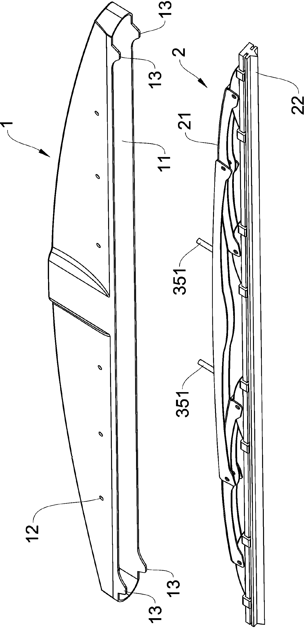
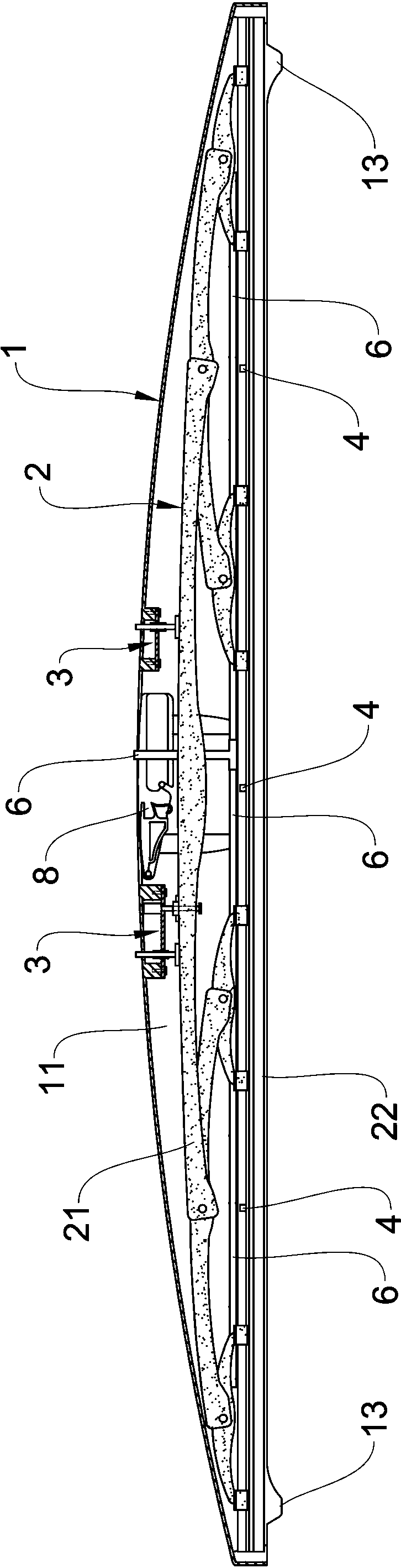
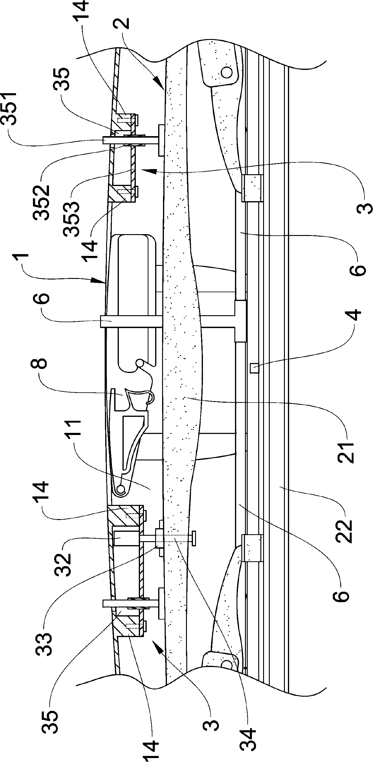
[0021] Such as Figure 1 to Figure 5 As shown, a wiper blade with a lifting function according to the present invention includes a protective cover 1 and a wiper 2, wherein the protective cover 1 is provided with a cavity 11 for accommodating the wiper 2, and the wiper 2 is arranged on In the cavity 11, between the top of the wiper 2 and the inner top wall of the cavity 11, there is also a push mechanism 3 that can make the wiper 2 extend out of the cavity 11 or retract into the cavity 11. On the top of the protective cover 1 There is also a fastening hole 8 for fastening with the wiper swing arm on the car. The structure of this fastening hole 8 is basically the same as the structure of the fastening hole on the traditional wiper.

[0022] Among them, such as figure 2 and image 3 As shown, the pushing mechanism 3 can be composed of a micro numerical control motor 32 , a gear 33 , a screw or a rack 34 , and a pushing bracket 35 . Concretely can be assembled like this, pus...

Embodiment 2

[0029] The difference between the second embodiment and the first embodiment is that the protective cover is canceled and the telescopic support feet are added so that the wiper can be separated from the glass surface without brushing the glass surface. Contact, reduce glass high-temperature baking and heat transfer, delay the aging of the wiper rubber strip of the wiper, and achieve the purpose of prolonging its service life. The specific scheme of present embodiment two is like this: as Figure 6 and Figure 7 or Figure 8 and Figure 9 As shown, a wiper blade with a lifting function includes a wiper blade 2 , and a push mechanism 3 is provided on the top of the wiper blade 2 .

[0030] Among them, such as Figure 6 and Figure 7 As shown, the pushing mechanism 3 is composed of a micro numerical control motor 32 , a gear 33 , a screw or a rack 34 , a screw seat or a rack seat 36 . Specifically, it can be assembled in such a way that the miniature numerical control moto...


PUM


Abstract

The invention relates to a windscreen lifter with a lifting function. The windscreen lifter comprises a protective housing and a windscreen lifter, wherein a cavity slot for accommodating the windscreen lifter is formed in the protective housing; the windscreen lifter is arranged in the cavity slot; a pushing mechanism for enabling the windscreen lifter to extend out of the cavity slot or retractinto the cavity slot is further arranged between the top of the windscreen lifter and the inner top wall of the cavity slot; the pushing mechanism is composed of a micro gas cylinder and a pushing bracket; or the pushing mechanism consists of a micro numerical-control motor, a gear, a screw or a rack and a pushing bracket. A special protective mechanism is additionally arranged on the basis of a conventional windscreen lifter scheme, so that the windscreen lifter can be self-protected while not used for brushing glass, sunshine exposure or high-temperature baking is reduced, ageing of a water-scraping adhesive tape of the windscreen lifter is delayed, the service life of the windscreen lifter is prolonged, daily use cost of people is reduced, and natural environment is protected; and moreover, the additionally arranged protective mechanism has the advantages of being simple in structure, easy in implementation and compact in structure, not excessively increasing the size of the whole windscreen lifter, being good in adaptability with a vehicle, and the like.

Description

technical field [0001] The invention relates to the technical field of wipers applied to motor vehicles, trains, trams, airplanes and ships, in particular to an improved wiper that can prolong its service life. Background technique [0002] Wiper, also known as wiper, water dial, wiper or windshield wiper, is a device used to wipe off rain, dust, and dirt attached to the windshield of a vehicle. It can improve the visibility of the driver. Increase driving safety. Because of legal requirements, front windshield wipers are installed on automobiles almost everywhere, and rear windshield wipers are also installed on hatchbacks, SUVs, SUVs and other vehicles. Except automobiles, other means of transport or means of transportation are also provided with wipers, such as trains, trams, airplanes, ships, engineering vehicles and the like. Therefore, the wiper is a very widely used and very important mechanical component. Common wipers at present are generally composed of a wiper ...

Claims


Application Information

Patent Timeline
Patent Type & Authority Applications(China)
IPC IPC(8): B60S1/38
CPCB60S1/38B60S2001/3843
Inventor 彭志军
Owner 彭志军
Why Eureka
Try Eureka