Analysis system

An analysis system and analysis device technology, which is applied in the field of analysis systems for analyzing samples, can solve problems such as mechanical abnormalities and pressure data abnormalities, and achieve the effect of simple structure

Active Publication Date: 2020-03-03
HITACHI HIGH-TECH CORP
View PDF9 Cites 1 Cited by
  • Summary
  • Abstract
  • Description
  • Claims
  • Application Information

AI Technical Summary

Problems solved by technology

However, the abnormality of the pressure data in Patent Document 1 may be caused not only by the fluidity of the sample and the drug, but also by a mechanical abnormality of the analysis device.

Method used


Image

  • Analysis system
  • Analysis system
  • Analysis system

Examples


no. 1 approach

[0055] [Analysis System Z]

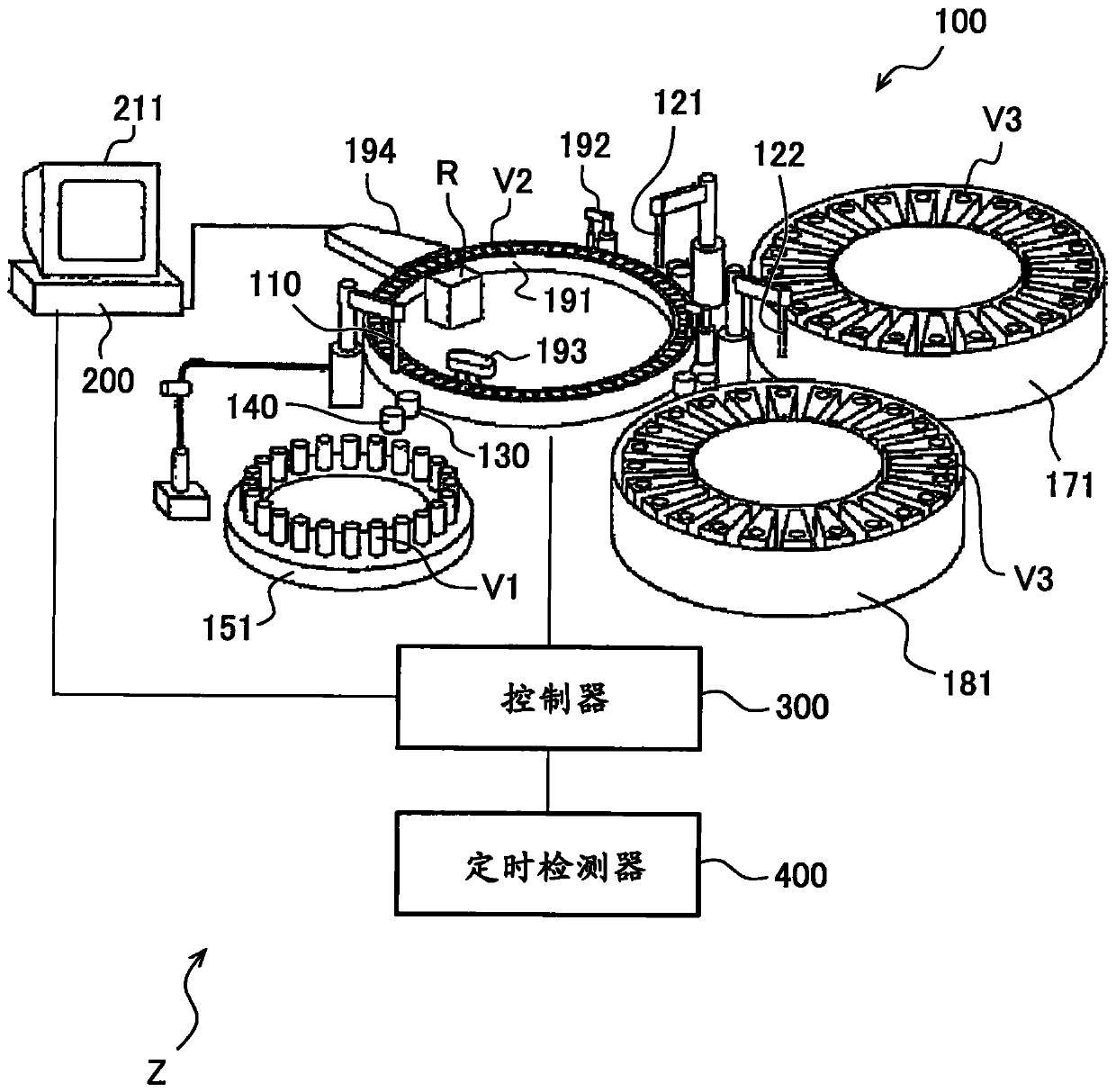
[0056] figure 1 It is a schematic configuration diagram of the analysis system Z of the first embodiment.

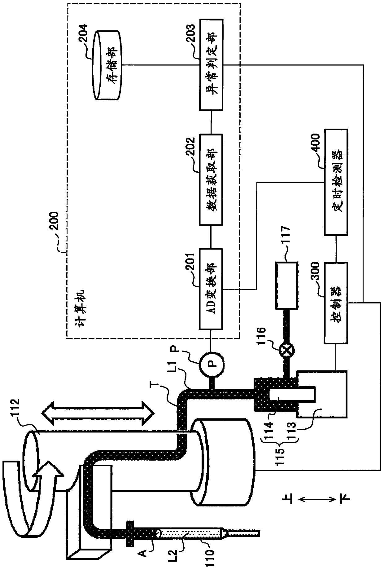
[0057] The analysis system Z includes an analysis device 100 , a computer (processing unit) 200 , a controller 300 , and a timing detector 400 .

[0058] The analysis device 100 includes a sample disk 151 , a first reagent disk 171 , a second reagent disk 181 , and a reaction disk 191 .

[0059] The sample disk 151 holds a sample container V1 for holding a sample. The first reagent disc 171 and the second reagent disc 181 hold reagent containers V3 for holding reagents. The reaction vessel V2 is held on the circumference of the reaction disk 191 .

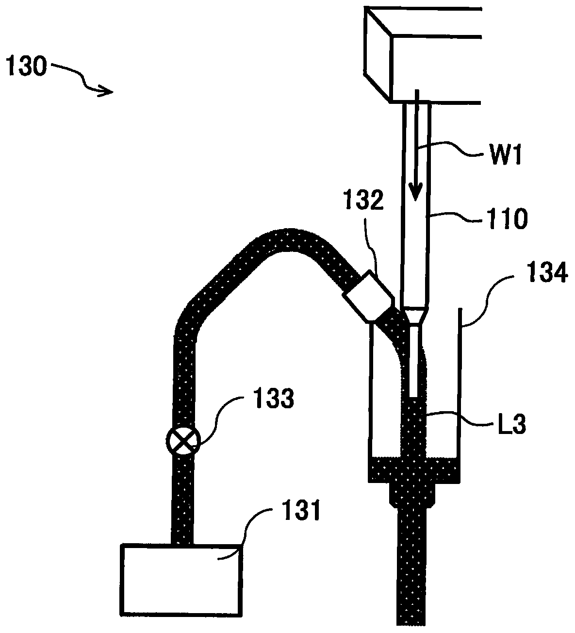
[0060] The analysis device 100 further includes a sample probe 110 , a first reagent probe 121 , a second reagent probe 122 , a cleaning unit 130 , a drying unit 140 , a stirring device 192 , a container cleaning unit 193 , and a light source R. In addition, for the cleaning part 130 and the ...

no. 2 approach

[0193] As the main cause of the change in the pressure data of the analysis device 100, differences in installation conditions and operating conditions of the analysis device 100 can be cited. For example, depending on the ambient temperature, humidity, air pressure, and temperature of supplied pure water (system fluid L1 ) at the location where the analyzer 100 is installed, the pressure data may vary even under the same operating conditions. Therefore, when calculating the determination parameters, it is necessary to prepare pressure data acquired under various environmental conditions. On the other hand, determination parameters acquired for various environmental conditions tend to have lower determination accuracy than determination parameters calculated from pressure data obtained under specific environmental conditions. Therefore, it is most preferable to select an appropriate determination parameter according to the installation conditions and operation conditions of th...

no. 3 approach

[0206] In addition, as the determination parameter group selection method as in the second embodiment, different parameter groups may be selected for each operation.

[0207] That is, the determination score of each action is calculated for each determination parameter, and the parameter group with the smallest determination score (second condition) is selected among each action. For example, choose a combination such that the Figure 10 Select parameter e in the "external cleaning fluid spray confirmation", select parameter e in the "drying function confirmation", select parameter b in the "up and down rotation action confirmation" (in Figure 10 indicated by circle marks).

[0208] Thereby, abnormality determination can be performed using the optimum determination score for each operation. Accordingly, it is possible to improve the avoidance accuracy of erroneous determination.


PUM


Abstract

The present invention addresses the problem of detecting mechanical abnormalities in an analysis device by means of a simple configuration. The analysis system is characterized in that the analysis system is provided with an analysis device and an abnormality determination unit (203), and the analysis device is provided with a probe that sucks and discharges a liquid; a plunger (114) connected tothe probe via a flow path (T); an up-and-down rotation operation unit (112) that moves the position of the probe; and the pressure sensor (P), and a plunger (114) that is provided midway along a dispensing channel (T) connecting the probe and the plunger (114), and that is positioned closer to the plunger (114) than a portion of the dispensing channel (T) that moves integrally with the probe by means of the up-and-down rotation operation unit; an abnormality determination unit (203) for detecting the pressure of the liquid in the dispensing flow path (T), the abnormality determination unit (203) performing, on the basis of the pressure data detected by the pressure sensor (P), an analysis of the presence or absence of an abnormality with respect to an operation performed at the timing at which the pressure data is acquired.

Description

technical field [0001] The present invention relates to techniques for analysis systems that analyze samples. Background technique [0002] An analysis device is a device that produces a color change by mixing urine, blood, etc. sampled from the subject with a reagent corresponding to the content to be analyzed and causing it to react, and passes through a spectrophotometer This change is measured. [0003] Such an analysis device ejects a sample and a reagent into a reaction container through a dispensing probe. In order to discharge a certain amount, not only the suction and discharge actions of the dispensing probe, but also the accurate vertical movement, rotational movement, cleaning and drying must be performed. If an abnormality occurs in any of these operations, there is a possibility that a correct amount of the sample or reagent cannot be ejected. [0004] In Patent Document 1, an automatic analysis device is disclosed, "an automatic analysis device can be reali...

Claims


Application Information

Patent Timeline
Patent Type & Authority Applications(China)
IPC IPC(8): G01N33/52G01N35/10
CPCG01N33/52G01N35/1009G01N35/1002B01L3/021B01L2200/146
Inventor 岛田贤史山崎功夫西田正治
Owner HITACHI HIGH-TECH CORP
Why Eureka
Try Eureka