Light radiation field visual detection method and light radiation field visual detection equipment

A visual inspection and light field technology, applied in the field of light field inspection, can solve the problems of large human influence factors, large exposure, and large measurement errors, and achieve the effect of small human influence factors, simple detection process, and small measurement errors.

Pending Publication Date: 2020-03-06
深圳市博视科技有限公司
View PDF0 Cites 2 Cited by
  • Summary
  • Abstract
  • Description
  • Claims
  • Application Information

AI Technical Summary

Problems solved by technology

[0010] 1) Film imaging method: This is a classic method, but the disadvantage is that it needs to be developed, which is time-consuming and expensive to use (calculate the film cost);
[0011] 2) Fluorescence method: This method was developed and mainly used for radiotherapy. The disadvantage is that it is expensive (imported products), requires a large amount of exposure, and cannot save data
Due to the need for dark room observation and the fast decay of fluorescence brightness, the detection process is relatively laborious, and because the sharpness of the fluorescence boundary is not enough, the measurement error is relatively large;
[0012] 3) Fluorescence video recording method: it is composed of a detection board, a camera device, a data receiving and storage device, and is relatively complicated
The disadvantages are: ①Fixing the camera from above requires you to find the angle and distance yourself, and adjust the focus each time, which will affect the image clarity
②The reading is manual. You need to insert the SD card of the camera into the computer, use the player, manually determine the brightest frame of image, and pause the player. You need to be quick-sighted and read the data on the scale. too many factors

Method used


Image

  • Light radiation field visual detection method and light radiation field visual detection equipment
  • Light radiation field visual detection method and light radiation field visual detection equipment
  • Light radiation field visual detection method and light radiation field visual detection equipment

Examples


Embodiment Construction

[0072] The following will clearly and completely describe the technical solutions in the embodiments of the present invention with reference to the accompanying drawings in the embodiments of the present invention. Obviously, the described embodiments are only some, not all, embodiments of the present invention. Based on the embodiments of the present invention, all other embodiments obtained by persons of ordinary skill in the art without making creative efforts belong to the protection scope of the present invention.

[0073] In order to make the above objects, features and advantages of the present invention more comprehensible, the present invention will be further described in detail below in conjunction with the accompanying drawings and specific embodiments.

[0074] In order to enable those skilled in the art to better understand the solutions of the present invention, the following will clearly and completely describe the technical solutions in the embodiments of the p...


PUM


Abstract

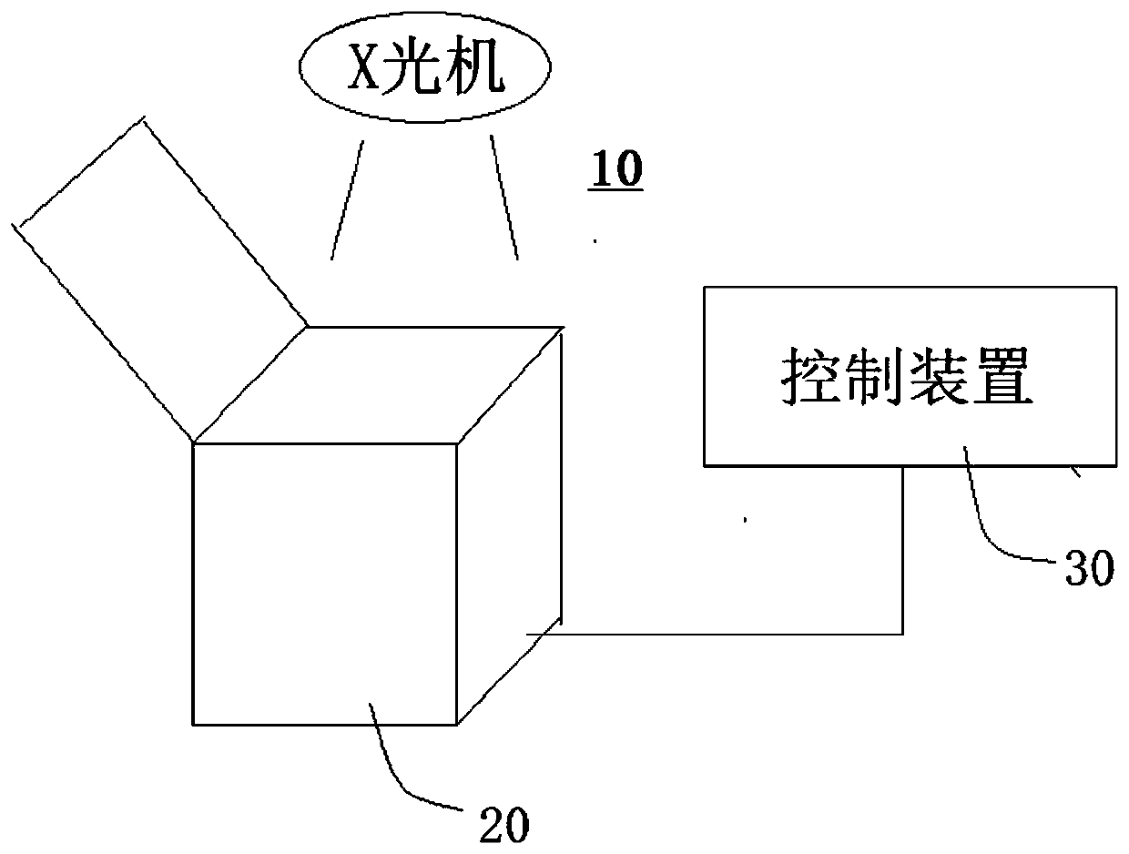
The invention relates to a light radiation field visual detection method and light radiation field visual detection equipment, and the method comprises the following steps: obtaining a light field image which is formed by visible light emitted by an X-ray machine radiation field indication lamp and shot by a camera module, wherein the light field image comprises an illuminated light field region;acquiring a radiation field image of X-rays emitted by an X-ray machine and shot by the camera module on a radiation field detection plate, wherein the radiation field image comprises a radiation field area; analyzing the light field image to obtain image attributes of the light field area; analyzing the radiation field image to obtain image attributes of the radiation field area; and calculatinga light field consistency parameter of the X-ray machine according to the light field area and the image attributes of the light field area, wherein the light field consistency parameter of the X-raymachine comprises an offset parameter of the light field area relative to the light field area.

Description

technical field [0001] The invention relates to a light field detection technology, in particular to a light field visual detection method and light field visual detection equipment for an X-ray machine. Background technique [0002] The light field refers to the area defined by the simulated light of the head of the X-ray machine (that is, the X-ray camera) on the incident surface. The radiation field refers to the projection of the X-ray beam of the X-ray machine on the incident surface. To be precise, it is the area defined by 50% of the dose intensity in the central area of ​​the beam. In clinical diagnostic examinations, since the field of view cannot be determined visually, the field of view is usually simulated with visible light. The light field consistency detection is mainly to verify the degree of coincidence between the light field formed by the light and the field formed by X-rays, including the degree of offset between the light field and the center or boundar...

Claims


Application Information

Patent Timeline
Patent Type & Authority Applications(China)
IPC IPC(8): A61B6/00
CPCA61B6/58
Inventor 郑永明杨建勇
Owner 深圳市博视科技有限公司
Why Eureka
Try Eureka