Pipeline sealant gluing device for floor heating pipeline mounting

A technology for installing sealant rings and pipes, which is applied in the direction of coating, spraying devices, and devices for coating liquid on the surface, etc. It can solve the problems of affecting the use of pipes, sealant flowing into pipes, and slow speed, so as to achieve fast glue coating, Avoid the effect of clogging the rubber tube

Active Publication Date: 2020-03-06
江西万上实业有限公司
View PDF14 Cites 4 Cited by
  • Summary
  • Abstract
  • Description
  • Claims
  • Application Information

AI Technical Summary

Problems solved by technology

[0004] In this way, when the sealant is applied to the pipeline, the speed is relatively slow, and one needs to hold the pipeline with one hand and the sealant with the other, and then apply the sealant to the thread of the pipeline, and manual glue application will cause the sealant to flow into the pipeline, which will affect the pipeline. usage of

Method used


Image

  • Pipeline sealant gluing device for floor heating pipeline mounting
  • Pipeline sealant gluing device for floor heating pipeline mounting
  • Pipeline sealant gluing device for floor heating pipeline mounting

Examples


Embodiment 1

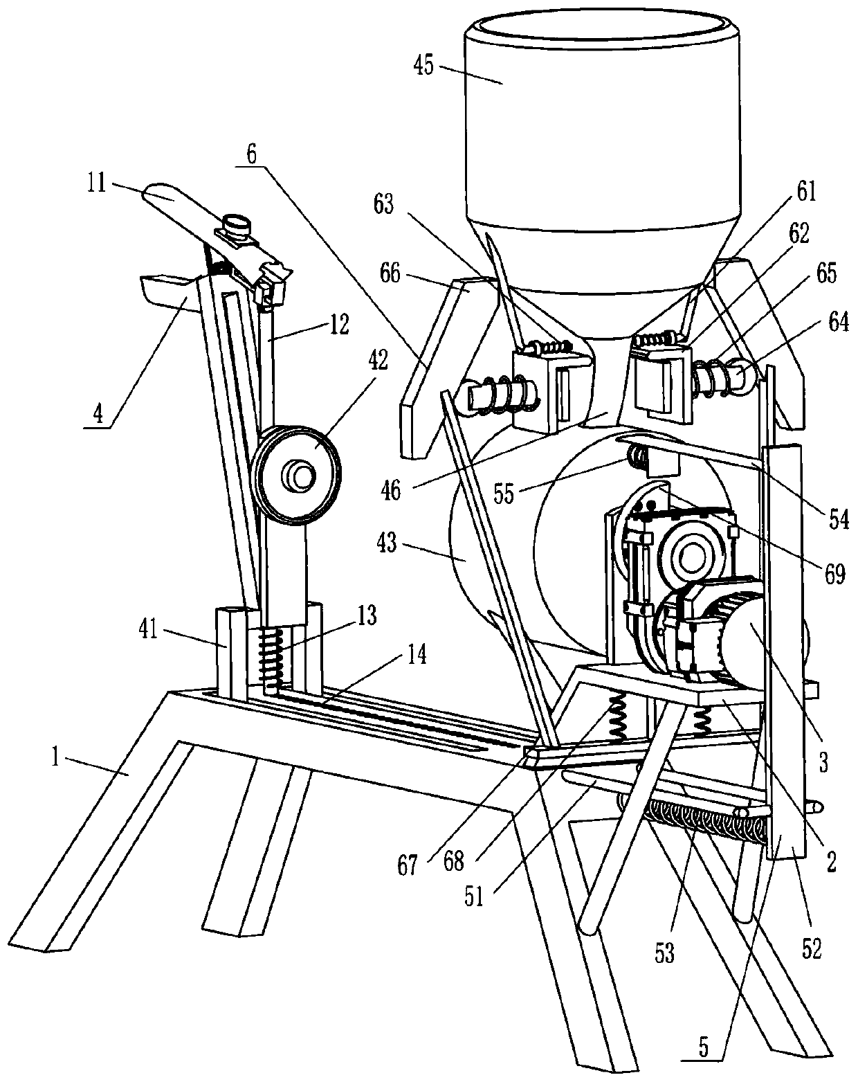
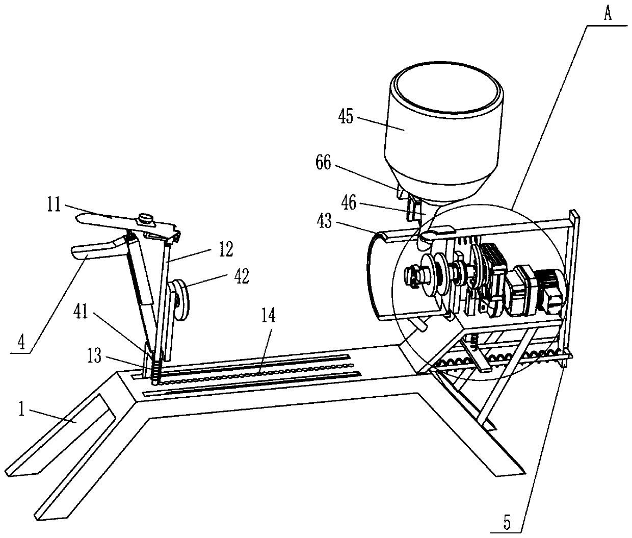
[0020] A kind of pipeline sealant ring applicator for floor heating pipeline installation, such as Figure 1-2 As shown, it includes a bottom frame 1, a mounting plate 2, a geared motor 3, a fixing device 4, and a clamping device 5. The right side of the bottom frame 1 is fixed with the mounting plate 2 through bolts, and the top of the mounting plate 2 is mounted with a geared motor through bolts. 3. The bottom frame 1 is provided with a fixing device 4 for fixing the floor heating pipeline, and the fixing device 4 is provided with a clamping device 5, and the clamping device 5 is used to block the sealant.

[0021] The fixing device 4 includes a sliding handle 41, a disk 42, a hollow tube 43, a T-shaped solid rod 44, a storage tube 45 and a rubber tube 46. The bottom frame 1 is provided with a sliding handle 41 in a sliding manner. 41 The middle part on the right side is provided with a disc 42 in a rotating manner, a hollow cylinder 43 is fixedly connected to the mounting p...

Embodiment 2

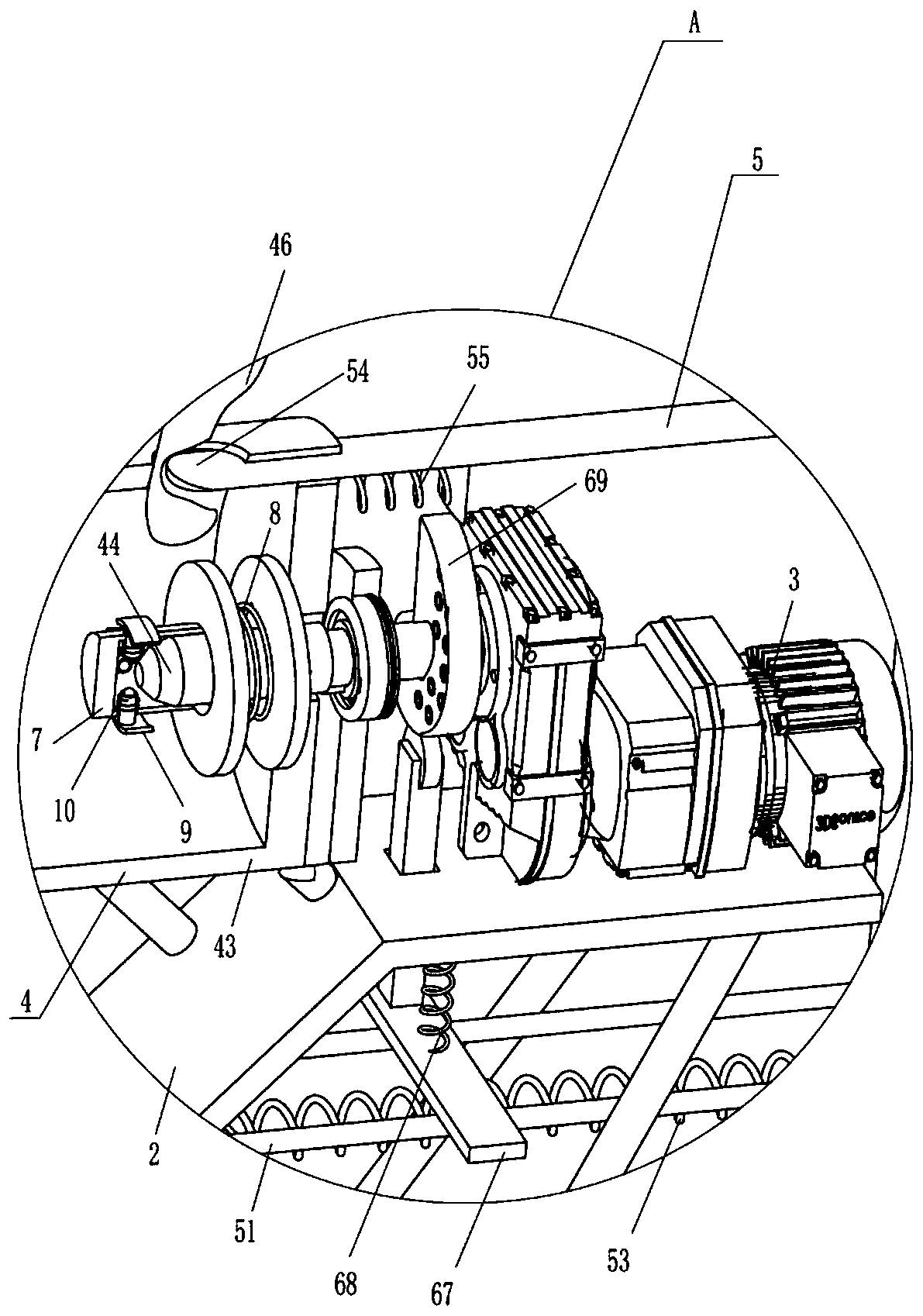
[0025] On the basis of Example 1, such as Figure 1-3 As shown, a material extruding device 6 is also included, and the material extruding device 6 includes an L-shaped slide bar 61, an L-shaped plate 62, a third spring 63, a T-shaped splint 64, a fourth spring 65, an inclined plate 66, a T-shaped plate 67, the fifth spring 68 and the cam 69, the front and rear sides of the storage tube 45 are fixedly connected with an L-shaped slide bar 61, the L-shaped slide bar 61 is slidably provided with an L-shaped plate 62, and the L-shaped plate 62 is connected to the L-shaped plate 62. A third spring 63 is connected between the sliding bars 61, and a T-shaped clamping plate 64 is slidably provided in the L-shaped plate 62, and a fourth spring 65 is connected between the T-shaped clamping plate 64 and the L-shaped plate 62. The elastic force of spring 63 is less than the fourth spring 65, and the sliding type is provided with T-shaped plate 67 on this mounting plate 2, is connected wit...

Embodiment 3

[0028] On the basis of Example 2, such as Figure 1-3 Shown, also comprise T-shaped hollow bar 7, the 6th spring 8, T-shaped clamping plate 9 and the 7th spring 10, be covered with T-shaped hollow bar 7 on this T-shaped solid bar 44, this T-shaped hollow bar 7 and The sixth spring 8 is connected between the T-shaped solid rods 44, and the T-shaped clamping plate 9 is evenly spaced and slidable on the T-shaped hollow rod 7, and the T-shaped clamping plate 9 is connected with the T-shaped hollow rod 7. There is a seventh spring 10, and the elastic force of the sixth spring 8 is greater than that of the seventh spring 10, and the inner end of the T-shaped clip 9 is in contact with the T-shaped solid rod 44.

[0029] Also includes movable handle 11, sliding lever 12 and eighth spring 13, movable handle 11 is installed with the mode of swinging on this sliding handle 41, and sliding type is provided with sliding lever 12 on this sliding handle 41, and this sliding lever An eighth ...


PUM


Abstract

The invention relates to a sealant gluing device, and particularly relates to a pipeline sealant gluing device for floor heating pipeline mounting. The pipeline sealant gluing device for floor heatingpipeline mounting aims at achieving the technical purposes that the pipeline thread position can be automatically glued, a sealant cannot flow into a pipeline, and the gluing speed is high. The pipeline sealant gluing device for floor heating pipeline mounting comprises a bottom frame, a mounting plate and the like, wherein the mounting plate is fixedly connected to one side of the bottom frame.According to the pipeline sealant gluing device, a sliding handle is pushed, a disc and a T-shaped solid rod can be driven to fix a floor heating pipeline, the floor heating pipeline can be driven torotate through a speed reduction motor, a top plate can be driven to make contact with or be separated from a rubber pipe through movement of the sliding handle, accordingly, the sealant can be discharged to the floor heating pipeline, and the floor heating pipeline thread position can be glued.

Description

technical field [0001] The invention relates to a sealant ring applicator, in particular to a pipeline sealant ring applicator for floor heating pipeline installation. Background technique [0002] In the north, floor heating has become a common way for people to heat in winter. Floor heating is a heating method that distributes heat by heating water to achieve heating purposes. The way of water heating is to lay floor heating pipes, and there are many joints and elbows in the floor heating pipes. Many floor heating pipes are not well sealed, and there will be water leakage. The sealant will play a more important sealing effect here. [0003] The operator first checks the joint surface and the size of the gap and squeezes out the sealant evenly to the thread of the pipe. The amount of coating should be based on the combination of the joint surface and then squeeze out a rubber ring slightly. The coating amount should not be too much, so as not to stain other surfaces or Bl...

Claims


Application Information

Patent Timeline
Patent Type & Authority Applications(China)
IPC IPC(8): B05C5/00B05C13/02B05C11/10B05B15/50
CPCB05C5/002B05C11/1002B05C13/02B05B15/50
Inventor 夏细云
Owner 江西万上实业有限公司
Why Eureka
Try Eureka