
Composite hammerhead pouring device and using method thereof

A composite hammer head and hammer head technology, which is applied to equipment for feeding molten metal into molds, casting molding equipment, and equipment for supplying molten metal, etc. It can solve problems such as lack of device protection, waste of molten steel, and large internal cooling effect , to achieve the effect of easy splicing and disassembly, lower cost of use, and convenient disassembly and splicing

Inactive Publication Date: 2020-03-06
HENGYANG HONGYU MACHINERY MANFUACTURING CO LTD
View PDF9 Cites 0 Cited by
  • Summary
  • Abstract
  • Description
  • Claims
  • Application Information

AI Technical Summary

Problems solved by technology

[0002] During the pouring process, the furnace water is poured from the bottom sprue. When the water is equal to the water inlet, the cold iron is placed at the bottom water inlet to block, and then the furnace water is poured in from the top water inlet. The water will The product is full. During the cooling process, the upper layer of the product solidifies and shrinks from the surface to the core, and the water at the riser replenishes the product. In this way, the product pouring process is realized, but serious shrinkage is found during the use of the product. hole phenomenon, therefore, there is an increasing demand for a composite hammer pouring device and method of use thereof
[0003] Most of the hammer pouring devices on the market cannot accurately control the amount of molten steel added during use, resulting in waste of molten steel during use, increasing the cost of use, and in the event of an accident, lack of control The device is protected in time. On the other hand, in the process of use, the disassembly of the pouring mold is cumbersome, which is not convenient for the production and removal of the composite hammer head. Large, close to the second water inlet, when the temperature of the poured molten iron is low, it is more likely to cause the inner runner to cool first, or block the inner runner, or make the inner runner flow poorly, and the casting effect of molten iron feeding is not good. The interior of the casting may be loose or shrinkage. Therefore, a compound hammer pouring device and its use method are proposed to solve the above problems

Method used


Image

  • Composite hammerhead pouring device and using method thereof
  • Composite hammerhead pouring device and using method thereof
  • Composite hammerhead pouring device and using method thereof

Examples


Embodiment Construction

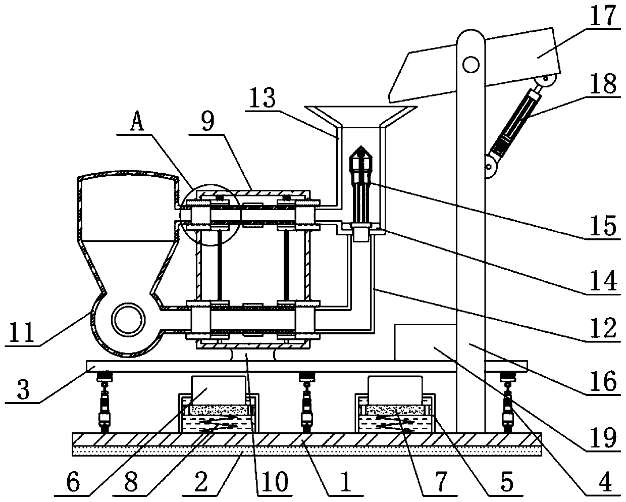
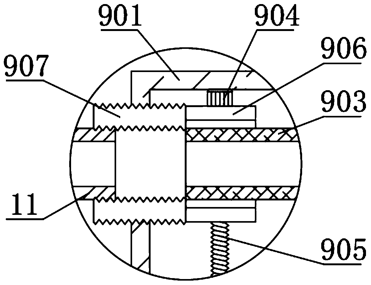
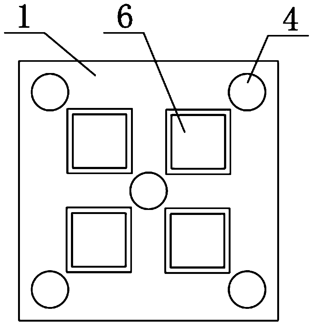
[0027] see Figure 1-6 , the present invention provides a technical solution:

[0028] A composite hammer pouring device and its use method, including a bottom plate 1, a connecting device 9, a hammer mold 11 and a partition device 15, the bottom end of the bottom plate 1 is fixedly connected with a rubber floor 2, and the top of the bottom plate 1 A support plate 3 is provided, the bottom end of the support plate 3 is fixedly connected with a pressure sensor 4, the bottom end of the pressure sensor 4 is fixedly connected with the bottom plate 1, and a fixed block is fixedly connected directly above the support plate 3 10, the top of the fixed block 10 is fixedly connected with a connecting device 9, the left side of the connecting device 9 is spirally connected with a hammer mold 11, and the right top of the connecting device 9 is spirally connected with a pouring bucket 13, the The bottom end of the right side of the connecting device 9 is spirally connected with a pouring ...


PUM


Abstract

The invention relates to the technical field of hammerhead pouring, and particularly relates to a composite hammerhead pouring device and a using method of the composite hammerhead pouring device. Thecomposite hammerhead pouring device comprises a bottom plate, a connecting device, a hammerhead mold and a separation device. A supporting plate is arranged over the bottom plate. A fixing block is fixedly connected over the supporting plate. The top end of the fixing block is fixedly connected with the connecting device. The hammerhead mold is spirally connected to the left side of the connecting device. A pouring hopper is spirally connected to the top end of the right side of the connecting device. A pouring pipeline is spirally connected to the bottom end of the right side of the connecting device. The top end of the pouring pipeline is fixedly connected with the bottom end of the pouring hopper. A limiting block is fixedly connected to the inner side of the bottom end of the pouringhopper. A separating device is arranged over the limiting block. Because a cold steel plate is arranged, the situation that when the temperature of poured molten iron is low, an inner pouring channelis caused to be cooled first, an inner pouring opening is blocked, or water flows in the inner pouring channel in an unsmooth manner is avoided, the effect of feeding molten iron to a casting is prevented from being poor, and loosening and hole shrinkage inside the casting are avoided.

Description

technical field [0001] The invention relates to the technical field of hammer pouring, in particular to a composite hammer pouring device and a method for using the same. Background technique [0002] During the pouring process, the furnace water is poured from the bottom sprue. When the water is equal to the water inlet, the cold iron is placed at the bottom water inlet to block, and then the furnace water is poured in from the top water inlet. The water will The product is full. During the cooling process, the upper layer of the product solidifies and shrinks from the surface to the core, and the water at the riser replenishes the product. In this way, the product pouring process is realized, but serious shrinkage is found during the use of the product. hole phenomenon, and therefore, there is an increasing need for a composite hammer pouring device and method of use thereof. [0003] Most of the hammer pouring devices on the market cannot accurately control the amount of...

Claims


Application Information

Patent Timeline
Patent Type & Authority Applications(China)
IPC IPC(8): B22D35/04B22D39/04B22C9/08
CPCB22C9/082B22D35/04B22D39/04
Inventor 刘传华欧阳淑兵付清华
Owner HENGYANG HONGYU MACHINERY MANFUACTURING CO LTD
Learn More