
Carbon fiber automobile front floor compression molding method

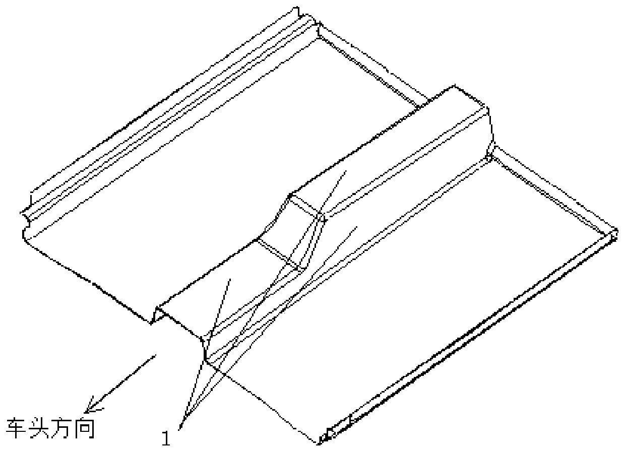
An automobile front floor, molding technology, applied to other household appliances, household appliances, household components and other directions, can solve the problems of non-overlapping of prepregs, unfriendly production environment, product scrapping, etc., and achieves obvious weight reduction effect. Good appearance quality and good thickness consistency

Inactive Publication Date: 2020-03-06
AVIC COMPOSITES
View PDF3 Cites 3 Cited by
  • Summary
  • Abstract
  • Description
  • Claims
  • Application Information

AI Technical Summary

Problems solved by technology

[0002] At present, most of the common front floors in the automobile industry are made of metal, with integral stamping and forming, and block stamping and reassembly. With the rapid development of new energy vehicles, the weight reduction of automobile bodies has become the focus, so carbon fiber is used in automobile bodies. There are also more and more parts. Among them, the front floor body is the main load-bearing part, which has been made using VARI, RTM and other molding methods. These molding methods are roughly laid by dry fiber cloth, and the liquid resin is introduced and then cured; The VARI molding process requires the use of a variety of auxiliary materials, such as release cloth, porous isolation film, diversion net, injection tube, vacuum tube, vacuum bag, sealing strip, etc. The RTM molding process requires the use of injection tubes, vacuum tubes, etc. Auxiliary materials are all disposable and non-recyclable, which makes the production environment unfriendly; moreover, the airtightness requirements are strict during the resin introduction and curing process, and once the air leaks, the product will be scrapped; the molding method adopted in the present invention does not need to be considered at all. However, the molded carbon fiber front floor body will face two major technical problems: one is that the prepregs cannot be overlapped during the prepreg laying process, and the other is the thickness uniformity of different areas of the larger shaped molded parts. There is no defect in the corner area, and the profile tolerance meets the requirements

Method used


Image

  • Carbon fiber automobile front floor compression molding method

Examples


Embodiment Construction

[0024] In order to make the purpose, technical solutions and advantages of the embodiments of the present invention more clear, the technical solutions in the embodiments of the present invention will be clearly and completely described below in conjunction with the drawings in the embodiments of the present invention. Apparently, the described embodiments are some, not all, embodiments of the present invention. Based on the embodiments of the present invention, all other embodiments obtained by persons of ordinary skill in the art without making creative efforts belong to the protection scope of the present invention.

[0025] The features of various aspects of the embodiments of the present invention will be described in detail below. In the following detailed description, numerous specific details are set forth in order to provide a thorough understanding of the present invention. It will be apparent, however, to one skilled in the art that the present invention may be pra...


PUM


Abstract

The invention belongs to the technical field of traffic facilities, and relates to a carbon fiber automobile front floor compression molding method. A carbon fiber prepreg is used as a molding material, and a prepreg molding process is used as a basis, and the compression molding method comprises the following steps of prepreg cutting; die maintaining; prepreg paving, specifically, paving the cutprepreg layer by layer according to the design laying area and the laying angle, and selecting 12K carbon fibers and one-way belt prepreg as the prepreg; and closing the mold, pressurizing, heating, curing, and then demolding. Compared with an existing molding process method, the carbon fiber automobile front floor body manufactured by the method has the advantages of no need of using an auxiliarymaterial, no air tightness requirement and environmental friendliness, the appearance quality is good, the corner area is free of defects, the product thickness of different areas is different, and the profile tolerance meets the requirements.

Description

technical field [0001] The invention belongs to the technical field of traffic facilities and relates to a carbon fiber front floor molding method for automobiles. Background technique [0002] At present, most of the common front floors in the automobile industry are made of metal, with integral stamping and forming, and block stamping and reassembly. With the rapid development of new energy vehicles, the weight reduction of automobile bodies has become the focus, so carbon fiber is used in automobile bodies. There are also more and more parts. Among them, the front floor body is the main load-bearing part, which has been made using VARI, RTM and other molding methods. These molding methods are roughly laid by dry fiber cloth, and the liquid resin is introduced and then cured; The VARI molding process requires the use of a variety of auxiliary materials, such as release cloth, porous isolation film, diversion net, injection tube, vacuum tube, vacuum bag, sealing strip, etc....

Claims


Application Information

Patent Timeline
IPC IPC(8): B29C70/34B29C70/54B29L31/30
CPCB29C70/345B29C70/54B29L2031/30
Inventor 刘宾宾马俊祥胡孝才丁晓春
Owner AVIC COMPOSITES
Features
  • Generate Ideas
  • Intellectual Property
  • Life Sciences
  • Materials
  • Tech Scout
  • Unparalleled Data Quality
  • Higher Quality Content
  • 60% Fewer Hallucinations
Learn More