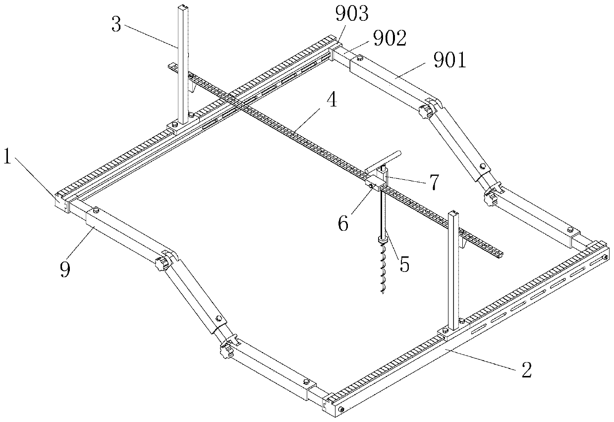
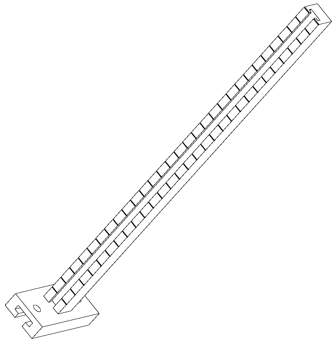
Device used for forming holes in surface of side slope model

A slope and model technology, applied in the direction of supporting devices, drilling equipment and methods, drilling equipment, etc., can solve problems such as the inability to guarantee the spacing of holes, the inability to guarantee the vertical state, and the large initial stress of model piles, etc., to achieve structural Simple, time-saving, and easy-to-operate effects

Pending Publication Date: 2020-03-06
TIANJIN RES INST FOR WATER TRANSPORT ENG M O T
View PDF0 Cites 0 Cited by
  • Summary
  • Abstract
  • Description
  • Claims
  • Application Information

AI Technical Summary

Problems solved by technology

The traditional method is that before the test starts, it is necessary to convert according to the pile spacing and slope slope of the pile foundation plan of the wharf, draw the points of each pile on the slope, and use iron rods to insert vertically into the soil to form holes. Then the piles of the entire wharf model are aligned with the holes and inserted into the bank slope model, but the above method cannot guarantee that the spacing of the holes is accurate, and at the same time it cannot be guaranteed that the holes formed are vertical, resulting in the initial stress of the model piles too large to be realistic

Method used


Image

  • Device used for forming holes in surface of side slope model
  • Device used for forming holes in surface of side slope model
  • Device used for forming holes in surface of side slope model

Examples


Embodiment Construction

[0043] It should be noted that, in the case of no conflict, the embodiments of the present invention and the features in the embodiments can be combined with each other.

[0044]In describing the present invention, it should be understood that the terms "center", "longitudinal", "transverse", "upper", "lower", "front", "rear", "left", "right", " The orientations or positional relationships indicated by "vertical", "horizontal", "top", "bottom", "inner" and "outer" are based on the orientations or positional relationships shown in the drawings, and are only for the convenience of describing the present invention and Simplified descriptions, rather than indicating or implying that the device or element referred to must have a particular orientation, be constructed and operate in a particular orientation, and thus should not be construed as limiting the invention. In addition, the terms "first", "second", etc. are used for descriptive purposes only, and should not be interpreted ...


PUM


Abstract

The invention provides a device used for forming holes in the surface of a side slope model. The device comprises an upper horizontal rail, a lower horizontal rail and a connecting rod connecting theupper horizontal rail to the lower horizontal rail, wherein Z-direction brackets capable of moving in a length direction of the upper horizontal rail and the lower horizontal rail are arranged on theupper horizontal rail and the lower horizontal rail; a balance rail capable of being regulated to the horizontal direction is arranged between the Z-direction brackets; and an soil taking drill whichmoves in the length direction and is vertically downward is arranged on the balance rail. Through the upper horizontal rail with scales, the lower horizontal rail with scales and the Z-direction brackets, the device can regulate the position of the soil taking drill and soil drilling depth according to practical needs; the connecting rod is formed by hinging a plurality of telescopic joints, and length of the telescopic joints can be regulated to adapt to side slope models of various gradients; the soil taking drill is arranged on the balance rail which can be arranged in the horizontal direction, so that the drilling direction can be ensured to be vertical, and drilling position and drilling depth can be guaranteed to be precise. The device is simple in structure, is convenient in operation, saves time, and improves working efficiency.

Description

technical field [0001] The invention belongs to the technical field of geotechnical test auxiliary equipment, in particular to a device for forming holes on the surface of a slope model. Background technique [0002] In the geotechnical centrifugal model test, the wharf model as a whole is generally located on the slope of the bank slope, and the wharf model piles are vertically inserted into the slope. The traditional method is that before the test starts, it is necessary to convert according to the pile spacing and slope slope of the pile foundation plan of the wharf, draw the points of each pile on the slope, and use iron rods to insert vertically into the soil to form holes. Then the piles of the entire wharf model are aligned with the holes and inserted into the bank slope model, but the above method cannot guarantee that the spacing of the holes is accurate, and at the same time it cannot guarantee that the holes formed are vertical, resulting in the initial stress of ...

Claims


Application Information

Patent Timeline
Patent Type & Authority Applications(China)
IPC IPC(8): E21B7/02E21B7/04E21B12/00E21B15/04
CPCE21B7/02E21B7/04E21B12/00E21B15/04
Inventor 杨立功安晓宇裴文斌张宇亭纪文栋刘晓强左殿军
Owner TIANJIN RES INST FOR WATER TRANSPORT ENG M O T
Why Eureka
Try Eureka