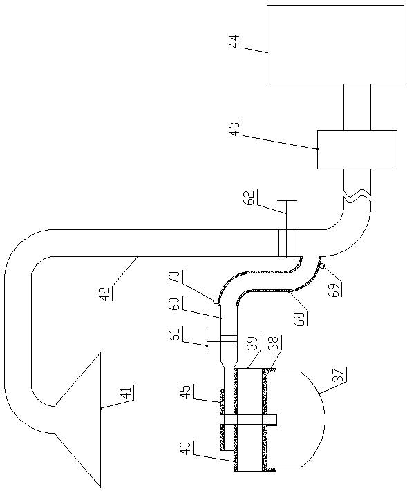
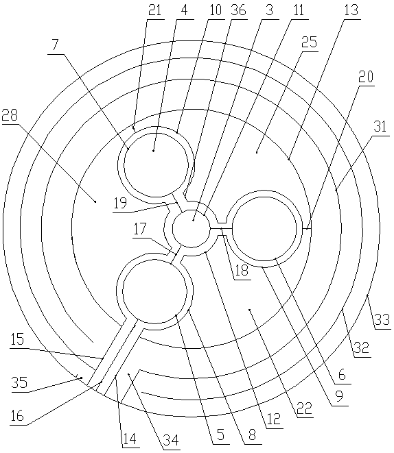
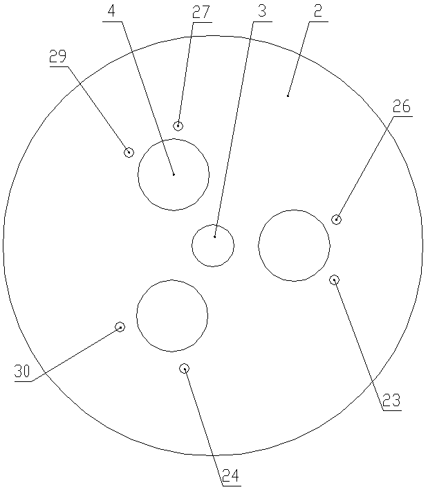
[0034] like Figure 1-Figure 5 As shown, the special cooling and dust collection device for electric arc furnace of the present invention includes a lower furnace cover 38, a middle furnace cover 39 and an upper furnace cover 40 which are sequentially arranged on the furnace body 37 from bottom to top, and the lower furnace cover 38 is a hollow water passage Water-cooled structure, the hollow structure of the middle furnace cover 39, a dust collection cover 41 is arranged directly above the upper furnace cover 40, a dust collection pipe 42 is connected to the top of the dust collection The outlet of the upper furnace cover 40 is connected with a bag dust collector 44, and the top of the upper furnace cover 40 is provided with a dust-collecting water-cooled furnace cover 45, and the centers of the lower furnace cover 38, the middle furnace cover 39, the upper furnace cover 40 and the dust-collecting water-cooled furnace cover 45 are provided with upper and lower furnace covers. The transparent feeding hole 3, the lower furnace cover 38, the middle furnace cover 39, the upper furnace cover 40 and the dust collection water-cooled furnace cover 45 are correspondingly provided with three electrode sockets 4, and the three electrode sockets 4 surround the center of the charging hole 3 The upper furnace cover 40 includes a bottom plate 1 arranged horizontally and a cover plate 2 above the bottom plate 1. Both the bottom plate 1 and the cover plate 2 are disc-shaped and arranged concentrically. The lower surface of the bottom plate 1 is provided with a fireproof partition Thermal material layer (not shown in the figure), the upper surface of the bottom plate 1 is provided with a central water cooling structure surrounding the feeding hole 3 and three electrode insertion holes 4 and an edge water cooling structure located on the outer periphery of the central water cooling structure, and the lower cover plate 2 The surface is fixedly connected to the top of the central water cooling structure and the edge water cooling structure.
[0035] The central water cooling structure includes a first annular strip 5, a second annular strip 6, a third annular strip 7, a fourth annular strip 8, a fifth annular strip 9, The sixth circular strip 10, the seventh circular strip 11, the eighth circular strip 12, the ninth circular strip 13, the first straight strip 14, the second straight strip 15, The first straight partition 16, the second straight partition 17, the third straight partition 18, the fourth straight partition 19, the fifth straight partition 20 and the sixth straight partition 21;
[0036] The diameter of the first annular strip 5, the second annular strip 6 and the third annular strip 7 is equal to the diameter of the electrode jack 4, the first annular strip 5, the second annular strip Shaped strip 6 and the 3rd annular strip 7 are arranged along the circumference edge of three electrode jacks 4 respectively, and the 4th annular strip 8, the 5th annular strip 9 and the 6th annular strip The diameters of the plates 10 are equal, the diameter of the fourth annular strip 8 is greater than the diameter of the first annular strip 5, and the fourth annular strip 8 is concentrically sleeved outside the first annular strip 5 A first annular passage is formed, the fifth annular strip 9 is concentrically sleeved on the outside of the second annular strip 6 to form a second annular passage, and the sixth annular strip 10 is concentrically sleeved on the third annular The outside of shape strip 7 forms the 3rd annular channel, and the diameter of the seventh annular strip 11 is equal to the diameter of feeding hole 3, and the diameter of the eighth annular strip 12 is greater than the diameter of the seventh annular strip 11 , the seventh annular strip 11 is arranged along the circumference of the feeding hole 3, and the eighth annular strip 12 is concentrically sleeved outside the seventh annular strip 11 to form a fourth annular passage; the fourth annular passage Respectively communicate with the first annular passage, the second annular passage and the third annular passage through two short strips 36;
[0037] The ninth annular strip 13 is arranged concentrically with the feeding hole 3, and the fourth annular strip 8, the fifth annular strip 9 and the sixth annular strip 10 are the ninth annular strip 13 The inside of; the first straight partition 16 is arranged along the radial direction of the feed hole 3, and the length direction of the first straight partition 16 passes through the center of the first circular strip 5, the first straight strip 14 and the second The straight strips 15 are positioned on the left and right sides of the first straight partition 16 and are arranged parallel to the first straight partition 16. The outer ends of the first straight strip 14, the second straight strip 15 and the first straight partition 16 are connected to The circumference of base plate 1 is flush, and the inner ends of the first straight strip 14 and the second straight strip 15 pass through the ninth circular strip 13 and are connected with the fourth circular strip 8, and the first straight partition The inner end of 16 is connected with the first annular strip 5 through the 4th annular strip 8; The second straight partition 17, the third straight partition 18 and the fourth straight partition 19 are respectively positioned Between the short strips 36, the two ends of the second straight partition 17 are connected to the seventh circular strip 11 and the first circular strip 5, and the two ends of the third straight partition 18 are connected to the seventh circular strip. Plate 11 and the second annular strip 6, the fourth straight partition 19 two ends connect the seventh annular strip 11 and the third annular strip 7; the two ends of the fifth straight partition 20 are connected respectively The fifth annular strip 9 and the ninth annular strip 13, the two ends of the fifth straight partition 20 are respectively connected with the fifth annular strip 9 and the ninth annular strip 13, the sixth straight Both ends of the partition 21 are respectively connected to the sixth annular strip 10 and the ninth annular strip 13;
[0038] The first straight slat 14 and the first straight partition 16 form a straight water inlet channel, the second straight slat 15 and the first straight partition 16 form a straight water outlet channel, and the straight water inlet and the half circle of the first annular channel successively , the first third of the fourth annular channel, the second annular channel, the second third of the fourth annular channel, the third annular channel, the third third of the fourth annular channel One circle is connected with the straight water outlet channel to form the first cooling water circuit;
[0039] The upper surface of the base plate 1, the lower surface of the cover plate 2, the fourth circular strip 8, the eighth circular strip 12, the fifth circular strip 9, the first straight strip 14, the fifth straight partition 20 and the ninth circular strip 13 to form a first cooling cavity 22, and the cover plate 2 is respectively provided with a first water inlet 23 and a the first water outlet 24;
[0040] The upper surface of the base plate 1, the lower surface of the cover plate 2, the fifth circular strip 9, the eighth circular strip 12, the sixth circular strip 10, the fifth straight partition 20, and the sixth straight partition 21 and the ninth circular strip 13 to form a second cooling chamber 25, and the cover plate 2 is respectively provided with a second water inlet 26 and a the second water outlet 27;
[0041] The upper surface of the base plate 1, the lower surface of the cover plate 2, the fourth circular strip 8, the eighth circular strip 12, the sixth circular strip 10, the sixth straight partition 21, the second straight strip 15 and the ninth circular strip 13 to form a third cooling cavity 28, and the cover plate 2 is respectively provided with a third water inlet 29 at the position adjacent to the sixth straight partition 21 and the second straight strip 15 and the third water outlet 30.
[0042] The edge water cooling structure comprises a tenth annular strip 31 , an eleventh annular strip 32 and a twelfth annular strip 33 whose diameters increase sequentially, and the diameter of the tenth annular strip 31 is larger than The diameter of the ninth circular strip 13, the tenth circular strip 31 is concentrically set on the outside of the ninth circular strip 13, and the eleventh circular strip 32 is concentrically set on the tenth circular strip. On the outside of the ring-shaped strip 31, the twelfth annular strip 33 is concentrically sleeved outside the eleventh annular strip 32, and the twelfth annular strip 33 is along the outer edge of the base plate 1 and The outer edge of the cover plate 2 is set;
[0043] The tenth circular strip 31 , the eleventh circular strip 32 and the twelfth circular strip 33 are provided with notches, and the notches are located at the first straight strip 14 and the second straight strip 15 On both sides, the ninth annular strip 13 and the tenth annular strip 31 form the fifth annular passage, the tenth annular strip 31 and the eleventh annular strip 32 form the sixth annular passage, The eleventh annular strip 32 and the twelfth annular strip 33 form the seventh annular passage, and the gap side of the fifth annular passage is connected with a third straight strip parallel to the first straight strip 14, The outer end of the third straight strip is flush with the outer circumference of the bottom plate 1, and the edge water inlet channel 34 is formed between the first straight strip 14 and the third straight strip. One end of the channel is connected, the other end of the sixth annular channel is connected with one end of the seventh annular channel, and the other end of the seventh annular channel is provided with an edge water outlet 35 adjacent to the second straight strip 15 .
[0044] The width of the fifth annular channel is smaller than the width of the sixth annular channel, and the width of the sixth annular channel is smaller than the width of the seventh annular channel.
[0045]The dust-collecting water-cooled furnace cover 45 includes a cylindrical body 46, a lower circular plate, a middle circular plate, an upper circular plate, a thirteenth circular strip 50, a fourteenth circular strip 51, and a fifteenth circular strip. Slats 52, 16th circular slats 53, 17th circular slats 54, 18th circular slats 55, 19th circular slats 56, fourth straight slats 57 , the fifth straight strip 58 and several baffle strips 59, the lower circular plate and the upper circular plate are horizontally arranged on the bottom and the top of the cylinder 46 respectively, the middle circular plate is horizontally arranged on the inside of the cylinder 46, and the middle The circular plate divides the interior of the cylindrical body 46 into an upper water cooling chamber and a lower dust collection chamber. A dust collection pipe 60 is connected between the outer circumference of the cylinder body 46 and the dust collection pipe 42, and the dust collection pipe 60 communicates with the dust collection chamber. , the dust collection pipe 60 is provided with a first air volume regulating valve 61, and the dust suction pipe 42 is provided with a second air volume regulating valve 62;
[0046] A feeding hole 3 and three electrode jacks 4 provided on the dust-collecting water-cooled furnace cover 45 are correspondingly arranged on the lower circular plate, the middle circular plate and the upper circular plate. The thirteenth circular strip 50 and the fourteenth circular Shaped strip 51, the 15th circular strip 52, the 16th circular strip 53, the 17th circular strip 54, the 18th circular strip 55, the 19th circular strip The upper side and the lower side of the shaped strip 56, the fourth straight strip 57, the fifth straight strip 58 and some baffle strips 59 are fixedly connected with the upper surface of the middle circular plate and the lower surface of the upper circular plate respectively;
[0047] The diameter of the thirteenth annular strip 50, the fourteenth annular strip 51, the fifteenth annular strip 52 is equal to the diameter of the electrode jack 4, the thirteenth annular strip 50, The fourteenth annular strip 51 and the fifteenth annular strip 52 are respectively arranged along the circumference edges of the three electrode jacks 4,
[0048] The diameter of the sixteenth circular strip 53 is equal to the diameter of the feeding hole 3, the diameter of the seventeenth circular strip 54 is greater than the diameter of the sixteenth circular strip 53, the sixteenth circular strip 53 53 is arranged along the circumference edge of the feeding hole 3, and the seventeenth annular strip 54 is concentrically sleeved outside the sixteenth annular strip 53 to form an eighth annular passage, and the eighteenth annular strip 55 The diameter is greater than the diameter of the nineteenth circular strip 56, the three electrode jacks 4 are located inside the nineteenth circular strip 56, the eighteenth circular strip 55 and the nineteenth circular strip The ninth annular passage is formed between 56, and the tenth annular passage is formed between the eighteenth annular strip 55 and the inner wall of the cylinder 46;
[0049] The fourth straight strip 57 and the fifth straight strip 58 are parallel and both parallel to the radial direction of the cylinder 46. A direct-flow water inlet channel 63 is formed between the fourth straight strip 57 and the fifth straight strip 58. The outer ends of the four straight strips 57 and the fifth straight strip 58 are fixedly connected to the cylinder 46, and the cylinder 46 is provided with a water inlet 64 communicating with the direct current water inlet channel 63, the fourth straight strip 57 and The inner end of the fifth straight strip 58 is fixedly connected to the outer wall of the seventeenth annular strip 54, and the inner end of the direct current water inlet channel 63 communicates with the eighth annular channel;
[0050] The inner circle of the nineteenth annular strip 56, the outer circle of the thirteenth annular strip 50, the outer circle of the fourteenth annular strip 51, and the outer circle of the fifteenth annular strip 52. The fourth cooling chamber is formed between the ring and the outer ring of the seventeenth annular strip 54, and the seventeenth annular strip 54 is provided with a first flow port 65 communicating with the eighth annular passage and the fourth cooling chamber, The 19th circular strip 56 is provided with a second flow port 66 which communicates with the fourth cooling cavity and the ninth annular passage, and the eighteenth circular strip 55 is provided with a connection with the tenth annular passage and the ninth annular passage. The third water outlet 67 of the channel, the cylinder 46 is provided with a water outlet 47 communicating with the tenth annular channel, the second water outlet 66 and the water outlet 47 are adjacent to the fourth straight strip 57, and the third water outlet 67 is adjacent The fifth straight strip 58 and several baffle strips 59 are all arranged in the fourth cooling cavity, and the first water outlet 65 communicates with the second water outlet 66 after passing through the several baffle strips 59 .
[0051] On the dust collection pipe 60, an outer casing 68 is arranged between the first air volume regulating valve 61 and the dust suction pipe 42. An annular cooling cavity is formed between the outer walls of the dust suction pipe 42. The outer sleeve 68 is provided with a water inlet pipe joint 69 adjacent to the first air volume regulating valve 61. The outer sleeve 68 is provided with an outlet pipe joint 70 adjacent to the dust suction pipe 42. The water inlet pipe Both the joint 69 and the outlet pipe joint 70 communicate with the inside of the annular cooling cavity.
[0052] When the present invention collects dust, most of the dust inside the furnace body 37 enters the dust collection chamber inside the dust collection water-cooled furnace cover 45 through the feeding hole 3, and under the action of the fan 43, a negative pressure is generated in the dust collection chamber, and the dust is discharged from the dust collection chamber. The dust collection chamber is sucked into the dust collection pipe 60, then enters the dust collection pipe 42, and finally enters the bag filter 44. A small part of the dust is recovered by the dust collection cover 41 through the feeding hole 3, and is also drawn by the fan 43. Suction down, enter in the bag filter 44. Due to the high temperature of the dust airflow in the dust collection chamber, in order to prevent the hot air from entering the bag filter 44 and burning the bag, an outer sleeve 68 is set on the dust collection pipe 60, and the air is discharged into the annular cooling chamber through the water inlet joint 69. The cold water is injected to cool down the hot air flow, and the hot water after heat exchange is discharged from the outlet pipe joint 70 .
[0053] The one-in-one-out water-cooling structure provided inside the water-cooling cavity on the upper part of the dust-collecting water-cooling furnace cover 45 mainly cools the upper end of the charging hole 3 to prevent the middle charging hole from being overheated and burned out. The airflow initially cools down.
[0054] The bottom plate 1 and the cover plate 2 in the upper furnace cover 40 are all made of rear steel plates, the slats and partitions of the central water cooling structure and the edge water cooling structure are all made of flat iron, and the upper and lower sides of the flat iron The sides are welded together with the bottom plate 1 and the cover plate 2 respectively. The refractory heat insulation material layer is located above the furnace, which plays the role of first-level heat insulation and cooling.
[0055] When the upper furnace cover 40 is in use, the first cooling water enters through the straight water inlet channel, and then follows the half circle of the first annular channel, the first third of the fourth annular channel, and the second annular channel. , the second third circle of the fourth annular channel, the third annular channel and the third third circle of the fourth annular channel, and the hot water exchanged is finally discharged through the straight water outlet channel.
[0056] The second cooling water enters the first cooling chamber 22 through the first water inlet 23, and the hot water after heat exchange is discharged from the first water outlet 24; the third cooling water enters the second cooling chamber 25 through the second water inlet 26, The hot water after heat exchange is discharged from the second water outlet 27 , the fourth cooling water enters the third cooling chamber 28 through the third water inlet 29 , and the hot water after heat exchange is discharged from the third water outlet 30 .
[0057] The fifth cooling water enters through the edge water inlet channel 34 , passes through the fifth annular channel, the sixth annular channel and the seventh annular channel in turn, and is discharged from the edge water outlet 35 . Since the cooling water with a lower temperature enters the fifth annular passage, in order to make the heat exchange of the cooling water more sufficient, the width of the fifth annular passage is set to be smaller than the width of the sixth annular passage, and the width of the sixth annular passage is smaller than that of the seventh annular passage. The width of the channel can achieve a better heat exchange effect.
[0058] The water-cooling process of the dust-collecting water-cooled furnace cover 45 is as follows: cold water enters through the water inlet 64, then enters the direct-flow water inlet channel 63, and then enters the eighth annular channel in turn, and the cold water directly enters the eighth annular channel, directly to the feeding hole 3. Perform heat exchange, which can greatly improve the cooling and cooling effect. Then the water enters the fourth cooling chamber, then enters the ninth annular channel and the tenth annular channel, and finally discharges through the water outlet hole 47.
[0059] This embodiment does not impose any formal restrictions on the shape, material, structure, etc. of the present invention. All simple modifications, equivalent changes and modifications made to the above embodiments according to the technical essence of the present invention belong to the protection of the technical solution of the present invention. scope.