Lubricating device for internal combustion engine

A lubricating device and internal combustion engine technology, which is applied in the direction of engine lubrication, pressure lubricant, engine cooling, etc., can solve the problems of improving the internal combustion engine, large axial length of the pin shaft, and increased length of the pin shaft, and achieve the effect of improving the output

Active Publication Date: 2021-11-05
MITSUBISHI MOTORS CORP
View PDF1 Cites 0 Cited by
  • Summary
  • Abstract
  • Description
  • Claims
  • Application Information

AI Technical Summary

Problems solved by technology

[0008] However, when the width of the bearing is set large, the width of the end of the connecting rod and the axial length of the pin need to be large
As a result, the length of the pin shaft increases, which is disadvantageous in improving the output of the internal combustion engine while reducing the size of the internal combustion engine

Method used


Image

  • Lubricating device for internal combustion engine
  • Lubricating device for internal combustion engine
  • Lubricating device for internal combustion engine

Examples


Embodiment Construction

[0027] Hereinafter, embodiments of the present invention will be described with reference to the accompanying drawings.

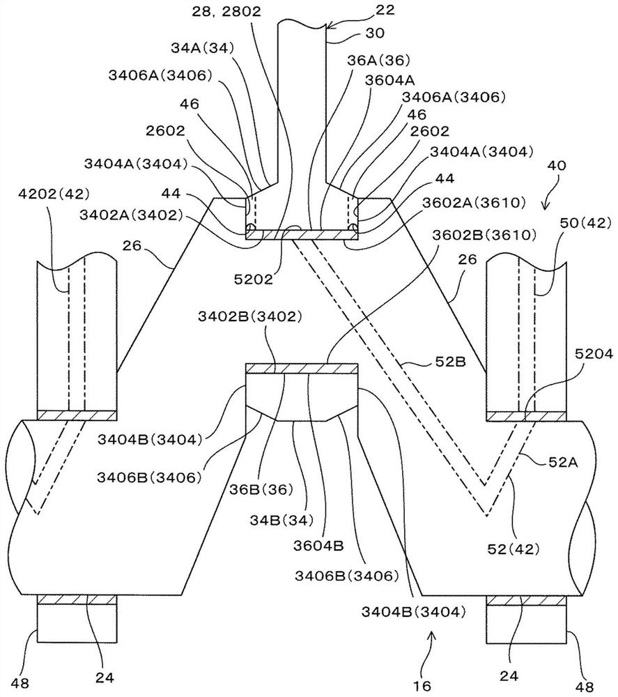
[0028] Such as Figure 8 As shown, internal combustion engine 10 includes: cylinder block 14 attached to crankcase 12, cylinder head (not shown) attached to cylinder block 14, crankshaft 16 rotatably supported by cylinder block 14, attached to cylinder block 14 and form the cylinder liner 18 of the cylinder wall surface 1802; the piston 20 slidably disposed on the cylinder wall surface 1802; and the connecting rod 22 connecting the crankshaft 16 and the piston 20.

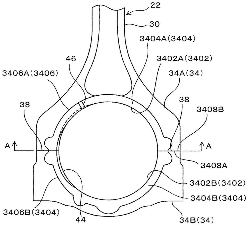
[0029] Such as figure 1 As shown, the crankshaft 16 includes a plurality of pairs of crank arms 26 disposed on the crank journal 24 and a plurality of pins 28 disposed between the top ends of the pairs of crank arms 26 .

[0030] Such as Figure 8 As shown, pin 28 of crankshaft 16 and piston pin 2002 of piston 20 are connected by connecting rod 22 .

[0031] Such as figure 1 As shown, annul...


PUM


Abstract

A lubricating device for an internal combustion engine, including a connecting rod, a first oil passage, a second oil passage and a groove. The connecting rod includes a first surface provided on one end portion in the longitudinal direction of the connecting rod, and a bearing for supporting a pin shaft of a crankshaft or a pin shaft of a piston is fitted to the first surface. The first oil passage is configured to supply oil between the outer peripheral surface of the pin shaft and the inner peripheral surface of the bearing. The second oil passage is provided at one end and configured to inject oil. A groove is formed on the first surface or on the outer peripheral surface of the pin shaft, extends in the circumferential direction of the pin shaft, and collects oil. The second oil passage is connected to the groove.

Description

technical field [0001] The invention relates to a lubricating device for an internal combustion engine. Background technique [0002] The internal combustion engine is provided with a lubricating device that sprays oil onto a cylinder wall surface on which a piston slides or a piston rear surface to lubricate the piston and the cylinder wall surface or to cool the piston, thereby improving the output of the internal combustion engine. [0003] In an internal combustion engine, the small end of the connecting rod is connected to the piston pin of the piston via a bearing, and the large end of the connecting rod is connected to the crankshaft pin via a bearing. [0004] JP3382867B2 discloses a lubricating device comprising an oil supply path open on the outer peripheral surface of a pin shaft of a crankshaft, a through hole provided in a bearing, and an oil injection path provided at a large end of a connecting rod, It communicates with the through hole and sprays oil onto th...

Claims


Application Information

Patent Timeline
Patent Type & Authority Patents(China)
IPC IPC(8): F01M1/06F01M1/08F01P3/08
CPCF01M1/06F01M1/08F01P3/08F01M2001/083
Inventor 上野慎司桐村宗孝
Owner MITSUBISHI MOTORS CORP
Why Eureka
Try Eureka