High-voltage ultrasonic wave generating circuit and high-voltage ultrasonic wave transmitting and receiving circuit

A high-voltage circuit and generation circuit technology, which is used in the generation of ultrasonic/sonic/infrasonic waves, material analysis using sonic emission technology, instruments, etc. It can solve problems such as the flow measurement of complex media and large-diameter pipelines that cannot be well solved. , to achieve the effect of limiting the voltage too high and protecting it from damage

Active Publication Date: 2020-03-10
CNOOC DEEPWATER DEV
View PDF8 Cites 1 Cited by
  • Summary
  • Abstract
  • Description
  • Claims
  • Application Information

AI Technical Summary

Problems solved by technology

[0004] The technical problem to be solved by the present invention is that, in view of the limitations of the high voltage resistance and high speed of electronic devices in the prior art, the voltage that can be realized is mostly about 1000V, and it cannot solve complex media and large-diameter pipelines well. To solve the defects of flow measurement, provide a high-voltage ultrasonic generating circuit and transceiver circuit

Method used


Image

  • High-voltage ultrasonic wave generating circuit and high-voltage ultrasonic wave transmitting and receiving circuit
  • High-voltage ultrasonic wave generating circuit and high-voltage ultrasonic wave transmitting and receiving circuit
  • High-voltage ultrasonic wave generating circuit and high-voltage ultrasonic wave transmitting and receiving circuit

Examples


Embodiment Construction

[0040] In order to have a clearer understanding of the technical features, purposes and effects of the present invention, the specific implementation manners of the present invention will now be described in detail with reference to the accompanying drawings.

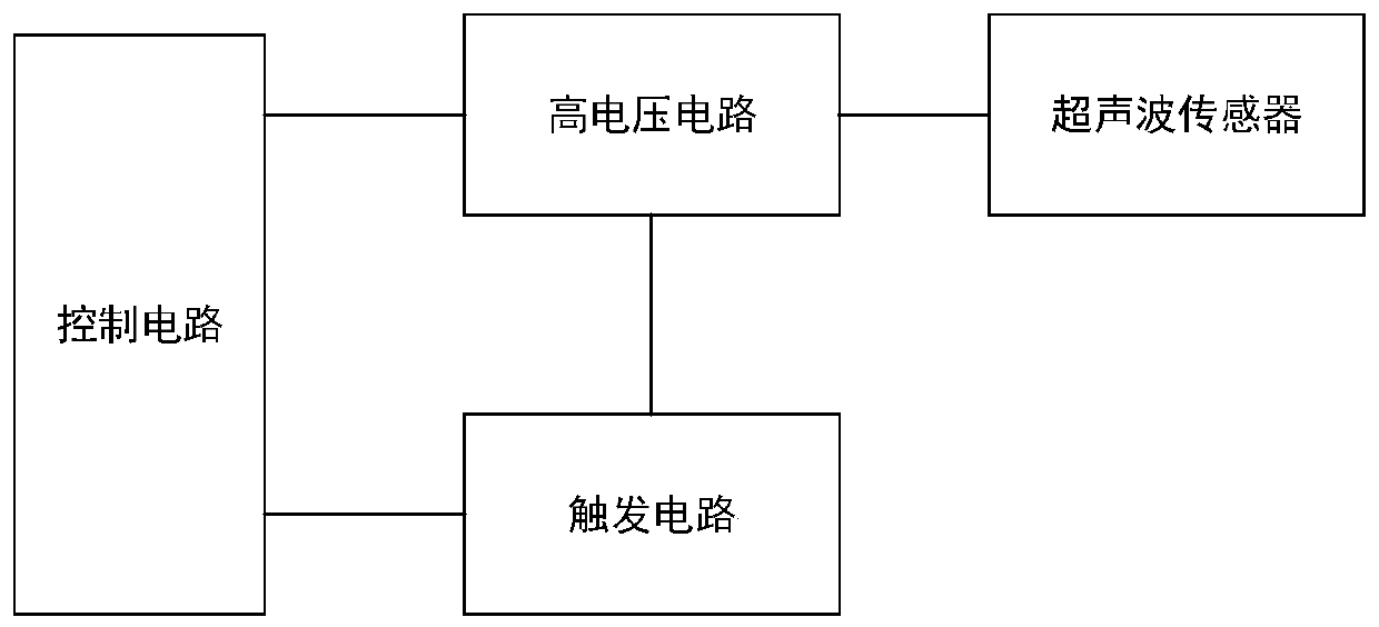
[0041] figure 1 It is a block diagram of the high-voltage ultrasonic generating circuit of the present invention, as figure 1 As shown, the present invention constructs a high-voltage ultrasonic generating circuit, including: a trigger circuit, a high-voltage circuit, and an ultrasonic sensor X1 connected in sequence, and a control circuit that provides start pulses for the trigger circuit and the high-voltage circuit respectively.

[0042] Wherein, the control circuit can control the trigger circuit to be in an unloaded state, control the high voltage circuit to boost to a preset high voltage, and keep the high voltage circuit disconnected from the ultrasonic sensor X1.

[0043] The control circuit can control the tri...


PUM


Abstract

The invention discloses a high-voltage ultrasonic wave generating circuit and a high-voltage ultrasonic wave transmitting and receiving circuit. The high-voltage ultrasonic wave generating circuit comprises a trigger circuit, a high-voltage circuit, an ultrasonic wave sensor X1 and a control circuit, wherein the trigger circuit, the high-voltage circuit and the ultrasonic wave sensor X1 are connected in sequence, and the control circuit provides starting pulses for the trigger circuit and the high-voltage circuit; the control circuit can control the trigger circuit to be in an unloaded state,control the high-voltage circuit to be boosted to a preset high voltage, and keep the high-voltage circuit disconnected from the ultrasonic wave sensor X1; the control circuit can control the triggercircuit to be in a loaded state and control the trigger circuit to trigger the high-voltage circuit to be connected with the ultrasonic wave sensor X1 through boosting, and high-frequency excitation is applied to the ultrasonic wave sensor X1 instantly. According to the invention, excitation is applied to the ultrasonic wave sensor through a three-electrode spark gap switch TRG, the switch not only can bear a high voltage of thousands of volts, but also is high in conduction speed which is of an ns-level, thereby enabling a high-voltage capacitor C1 to discharge rapidly to meet the high-frequency excitation required by the ultrasonic wave sensor.

Description

technical field [0001] The invention relates to the technical field of ultrasonic measurement, in particular to a high-voltage ultrasonic generating circuit and a transceiver circuit. Background technique [0002] At present, the drilling mud in the petroleum industry contains a large number of solid particles, and the liquid in crude oil exploitation contains various media such as crude oil, water, gas, sand, etc., which seriously attenuates the ultrasonic signal, resulting in too small amplitude of the received ultrasonic signal. The noise ratio is so low that it cannot even be measured. [0003] In order to solve the above problems, the existing technology mainly uses high voltage resistant electronic devices to generate high voltage to apply excitation signals to the transmitting sensor. Among them, the main representative literature is "Automation and Instrumentation" 2019 No. 3 paper "Based on ultrasonic sound intensity lossless UHV GIL Partial Discharge Detection Tec...

Claims


Application Information

Patent Timeline
Patent Type & Authority Applications(China)
IPC IPC(8): G01N29/14G01N29/34
CPCG01N29/14G01N29/34G01N2291/0226
Inventor 韦红术张俊斌魏裕森张凤辉张玺亮薛德栋
Owner CNOOC DEEPWATER DEV
Why Eureka
Try Eureka