
Electronic speed limit receiving and displaying device for facilitating vehicle running at optimal running speed

A technology of driving speed and display device, which is applied in the field of traffic driving, which can solve the problems of drivers consuming energy and being unable to drive, and achieve the effects of reducing the amount of capture, reducing the frequency of occurrence, and improving driving efficiency

Pending Publication Date: 2020-03-10
李德一
View PDF0 Cites 0 Cited by
  • Summary
  • Abstract
  • Description
  • Claims
  • Application Information

AI Technical Summary

Problems solved by technology

[0003] The technical problem to be solved by the present invention is that the existing vehicles tend to consume too much energy due to too many road speed limit signs during the driving process, and at the same time, it is impossible for the vehicle to drive at a relatively fast speed without exceeding the speed. Provide an electronic speed limit receiving and display device that facilitates the vehicle to run at an optimal speed, so as to solve the above problems

Method used


Image

  • Electronic speed limit receiving and displaying device for facilitating vehicle running at optimal running speed
  • Electronic speed limit receiving and displaying device for facilitating vehicle running at optimal running speed
  • Electronic speed limit receiving and displaying device for facilitating vehicle running at optimal running speed

Examples


Embodiment Construction

[0019] In the description of the present invention, it should be noted that the orientation or positional relationship indicated by the terms "vertical", "upper", "lower", "horizontal" etc. is based on the orientation or positional relationship shown in the drawings, and is only In order to facilitate the description of the present invention and simplify the description, it does not indicate or imply that the device or element referred to must have a specific orientation, be constructed and operated in a specific orientation, and thus should not be construed as limiting the present invention.

[0020] In the description of the present invention, it should also be noted that, unless otherwise clearly specified and limited, the terms "installation", "installation", "connection" and "connection" should be understood in a broad sense, for example, it may be a fixed connection, It can also be a detachable connection or an integral connection; it can be a mechanical connection or an ...


PUM


Abstract

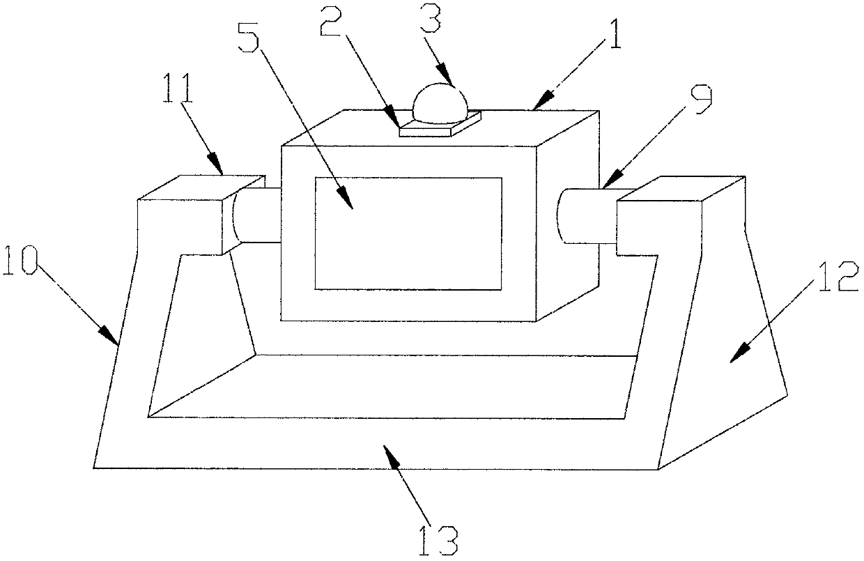
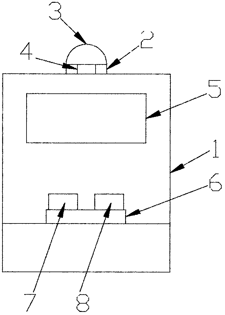
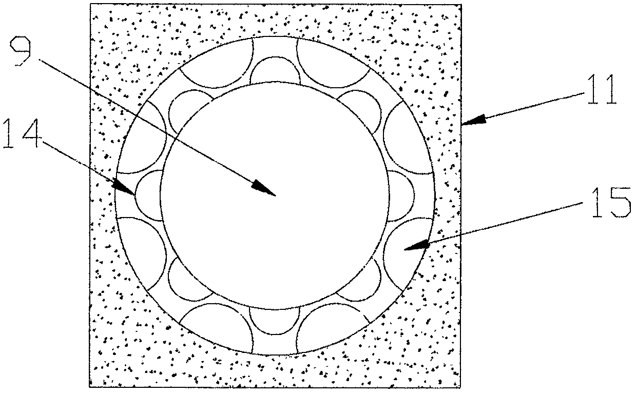
The invention discloses an electronic speed limit receiving and displaying device for facilitating a vehicle running at an optimal running speed, which comprises a display main body, and is characterized in that a connecting box is mounted on the top of the display main body, an indicating lamp assembly is mounted on the connecting box, a voice broadcasting system is arranged in the connecting box, an LED display screen is mounted outside the display main body, a main control module, a central processing unit and a wireless receiving module are arranged in the display main body, two connectingshafts are respectively mounted on two sides of the display main body, a supporting seat is mounted below the display main body, the supporting seat comprises two fixing blocks which are symmetrically arranged on the upper part and are of a bent structure, a supporting plate is vertically connected below each fixing block, a base is arranged between the bottom parts of the two supporting plates,one end of each connecting shaft is fixed at one side of the display main body, the other end of the connecting shaft is inserted into the corresponding fixing block of the supporting seat, a plurality of first limiting bulges are arranged on the outer wall, which is in contact with the fixing block, of each connecting shaft, a plurality of second limiting bulges are arranged on the inner wall, which is contact with the connecting shaft, of each fixing block, and the first limiting bulges and the second limiting bulges are clamped in a staggered mode.

Description

technical field [0001] The invention relates to the technical field of traffic driving, in particular to an electronic speed limit receiving and display device that facilitates the vehicle to run at an optimal speed. Background technique [0002] With the development of society, cars have gradually become an indispensable means of transportation for people to travel. While cars bring great convenience to people, they also bring certain hidden dangers. It is a traffic rule that every driver must obey. Speeding is a very unadvocated driving behavior, but in the actual driving process, because there are too many speed limit signs on the road, different road sections will correspond to different speed limit signs, drivers must control their cars below the maximum speed limit , drive as fast as possible without exceeding the speed limit, and at the same time keep checking the maximum speed limit of each section of the road. Cause traffic accidents, which is obviously unfavorabl...

Claims


Application Information

Patent Timeline
IPC IPC(8): G08G1/0967
CPCG08G1/096783
Inventor 李德一
Owner 李德一
Learn More