Optical module

A technology of optical modules and light beams, which is applied in the field of optical modules, can solve the problems of increased power consumption of the modulator on-chip loss system, and achieve the effects of increasing signal power, enhancing transmission performance, and reducing gain

Active Publication Date: 2020-03-10
ALIBABA GRP HLDG LTD
View PDF5 Cites 0 Cited by
  • Summary
  • Abstract
  • Description
  • Claims
  • Application Information

AI Technical Summary

Problems solved by technology

[0005] This application provides an optical module to solve the problem of increased system power consumption due to the large on-chip loss of the modulator in the traditional intensity modulation direct detection technology

Method used


Image

  • Optical module
  • Optical module
  • Optical module

Examples


Embodiment Construction

[0079] In the following description, numerous specific details are set forth in order to provide a thorough understanding of the application. However, the present application can be implemented in many other ways different from those described here, and those skilled in the art can make similar promotions without violating the connotation of the present application. Therefore, the present application is not limited by the specific implementation disclosed below.

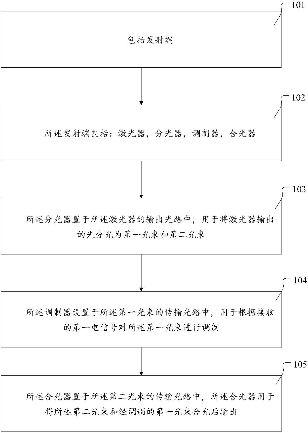
[0080] The first embodiment of the present application provides an optical module. Please see figure 1 , which is a flowchart of the first embodiment of the present application. The following combination figure 1 The first embodiment of the present application will be described in detail. Implementing the optical module includes the following steps:

[0081] Step S101, the optical module includes a transmitting end.

[0082] This step is used to provide information about the optical module, including the transmi...


PUM


Abstract

The invention provides an optical module. The optical module comprises a transmitting end, wherein the transmitting end comprises a laser, an optical splitter, a modulator and a light combiner; the optical splitter is arranged in an output light path of the laser and is used for splitting light output by the laser into a first light beam and a second light beam; the modulator is arranged in a transmission light path of the first light beam and is used for modulating the first light beam according to a received first electric signal; and the light combiner is arranged in a transmission light path of the second light beam and is used for combining the second light beam and the modulated first light beam and outputting the combined light. By adopting the optical module provided by the invention, the problem that the system power consumption is increased due to the fact that a modulator has relatively large on-chip loss in a traditional intensity modulation direct detection technology is solved.

Description

technical field [0001] The present application relates to the technical field of optical signal intensity modulation direct detection, and in particular to an optical module. Background technique [0002] The data center is composed of thousands of servers interconnected, and the connection distance is from a few meters (server to switch) to no more than 2 kilometers (switch to switch), and its connection rate is continuously increasing. The interface bandwidth of switches is steadily increasing according to Moore's Law, and since Gigabit Ethernet, optical communication technology has been widely used in the internal interconnection of data centers. [0003] Currently, the input / output (I / O) interface rate of the switch can reach 100G, and the modulation and demodulation method adopted is the traditional intensity-modulation direct-detection (IMDD), in which The pulse-amplitude modulation (PAM) electrical signal (PAM2) of the first stage is loaded onto the light through the...

Claims


Application Information

Patent Timeline
Patent Type & Authority Applications(China)
IPC IPC(8): H04B10/524H04B10/54H04B10/556H04B10/564H04B10/50
CPCH04B10/524H04B10/541H04B10/564H04B10/5561H04B10/505
Inventor 程竞驰谢崇进
Owner ALIBABA GRP HLDG LTD
Why Eureka
Try Eureka