A Method for Simultaneously Measuring Reflectance, Transmittance, Scattering Loss, and Absorption Loss of Highly Reflective/Highly Transmissive Optical Components

A technology of optical components and scattering loss, which is applied in the field of scattering loss and absorption loss, measuring the reflectivity and transmittance of high reflection/optical components, and can solve the problems of complex devices, time-consuming and labor-consuming, troublesome operation, etc., and achieve improved Effect of measurement accuracy, cost reduction, and gain reduction requirements

Active Publication Date: 2020-09-22
UNIV OF ELECTRONICS SCI & TECH OF CHINA
View PDF13 Cites 0 Cited by
  • Summary
  • Abstract
  • Description
  • Claims
  • Application Information

AI Technical Summary

Problems solved by technology

Using different devices to measure the single-point reflectance, transmittance and scattering loss of high-reflection / high-transmission optical components cannot guarantee that the test is at the same position and the components are in the same state, and the device is complex, cumbersome and time-consuming laborious
At present, there is no measurement method that can simultaneously measure the reflectance, transmittance, scattering loss and absorption loss of high reflection / high transmission optical elements. Efficiency, scattering loss and absorption loss, and it is necessary to meet the measurement method of two-dimensional scanning imaging

Method used


Image

  • A Method for Simultaneously Measuring Reflectance, Transmittance, Scattering Loss, and Absorption Loss of Highly Reflective/Highly Transmissive Optical Components
  • A Method for Simultaneously Measuring Reflectance, Transmittance, Scattering Loss, and Absorption Loss of Highly Reflective/Highly Transmissive Optical Components
  • A Method for Simultaneously Measuring Reflectance, Transmittance, Scattering Loss, and Absorption Loss of Highly Reflective/Highly Transmissive Optical Components

Examples


Embodiment Construction

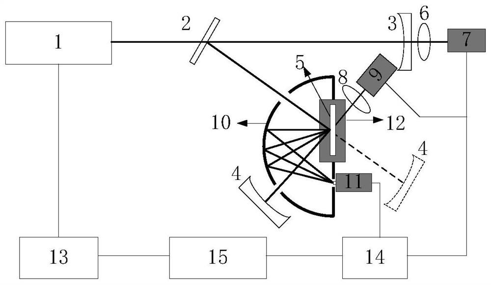
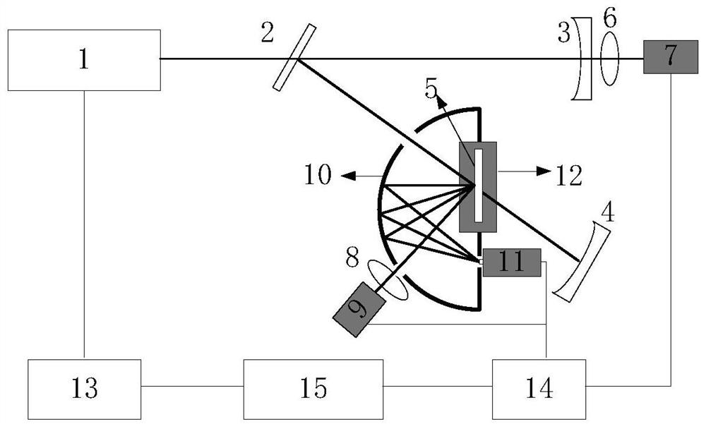
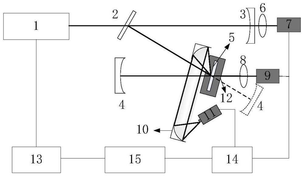
[0037] Combine below figure 1 and figure 2 The measurement system describes a method for simultaneously measuring reflectance, transmittance, scattering loss and absorption loss of high reflection / high transmission optical elements based on optical cavity ring down technology of the present invention.

[0038] The light source 1 is a continuous semiconductor laser, and the function generator card 13 is used to modulate the output synchronously with a square wave; according to the optical feedback optical cavity ring down technology, the laser is injected into a stable optical resonant cavity. A stable initial optical resonant cavity is formed by a plane high reflection mirror 2 and two identical plano-concave high reflection mirrors 3 and 4. The reflectivity of the high mirrors constituting the initial optical resonant cavity is greater than 99%, the initial optical resonant cavity is a stable optical resonant cavity or a confocal optical resonant cavity, and the length of t...


PUM

PropertyMeasurementUnit
reflectanceaaaaaaaaaa

Abstract

The invention relates to a method for simultaneously measuring the reflection, transmission, scattering and absorption of high reflection / high transmission optical elements. The method is based on optical cavity ring down technology, firstly measuring the ring down time τ of the initial optical resonant cavity 0 , and then add the high-reflection / high-transmission optical element to be tested, and measure the ring-down time τ of the test optical resonant cavity 1 , the reflectance / transmittance of the high reflection / high transmission optical element is obtained through calculation; the transmission / reflection light intensity signal and the scattered light intensity signal of the high reflection / high transmission optical element are measured at the same time and the transmission light intensity signal of the output cavity mirror is measured. Ratio, the reflectance, transmittance and scattering loss of the high reflection / high transmission optical element are obtained through calibration; the absorption loss of the optical element is obtained through the reflectance, transmittance and scattering loss. This measurement method can not only measure the reflectance, transmittance, scattering loss, and absorption loss of high reflection / high transmission optical elements, but also realize high-resolution two-dimensional imaging of their distribution.

Description

technical field [0001] The invention relates to the technical field for measuring the optical characteristics of high reflection / high transmission optical elements, in particular to a method based on optical cavity ring-down technology capable of measuring the reflectivity, transmittance, scattering loss and absorption loss of high reflection / optical elements Methods. Background technique [0002] High reflection / high transmission optical elements are widely used in high energy laser, gravitational wave detection, laser gyroscope and other technical fields. It is especially important to accurately measure the optical properties of highly reflective and highly transmissive components. [0003] The reflectivity measurement of highly reflective optical components is mainly based on optical cavity ring-down technology (Li Bincheng, Gong Yuan; Review of optical cavity ring-down high reflectivity measurement, "Laser and Optoelectronics Progress", 2010,47:021203). The invention p...

Claims


Application Information

Patent Timeline
Patent Type & Authority Patents(China)
IPC IPC(8): G01M11/02
CPCG01M11/00
Inventor 李斌成崔浩王静高椿明
Owner UNIV OF ELECTRONICS SCI & TECH OF CHINA
Why Eureka
Try Eureka