Vortex coil-type sunshine pumping fiber laser amplifier and amplification method thereof

A laser amplifier and pump fiber technology, applied in lasers, laser components, phonon exciters, etc., can solve the problem of not fully reflecting the advantages of sunlight-pumped optical communication systems in space applications, limiting system space applicability, low efficiency, etc. problem, to achieve the effect of improving energy transfer efficiency, simple structure and low energy consumption

Active Publication Date: 2019-09-06
SHANGHAI SATELLITE ENG INST
View PDF5 Cites 3 Cited by
  • Summary
  • Abstract
  • Description
  • Claims
  • Application Information

AI Technical Summary

Problems solved by technology

However, factors such as high threshold and low efficiency of the current sunlight-pumped laser amplifier system greatly limit the space applicability of the system, and cannot fully reflect the space application advantages of the sunlight-pumped optical communication system.

Method used


Image

  • Vortex coil-type sunshine pumping fiber laser amplifier and amplification method thereof
  • Vortex coil-type sunshine pumping fiber laser amplifier and amplification method thereof

Examples


Embodiment 1

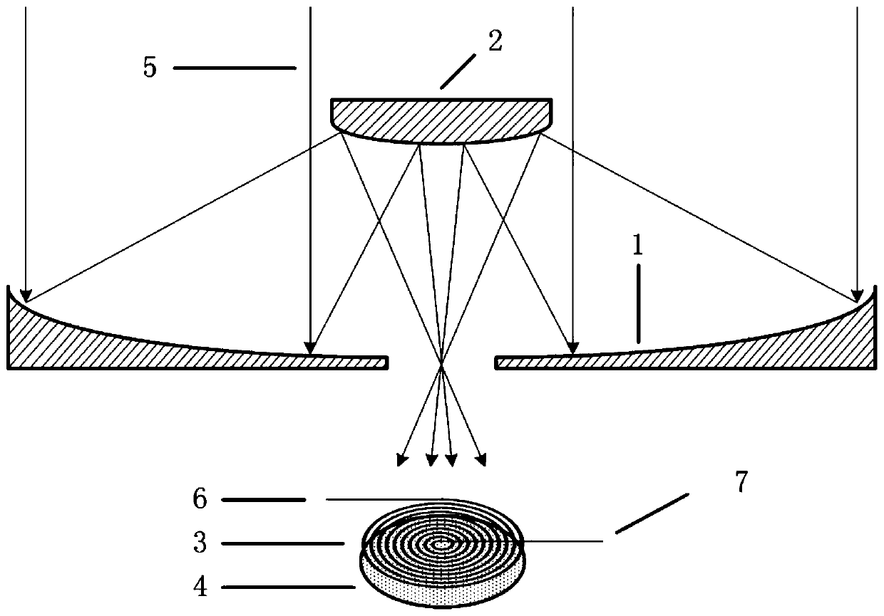
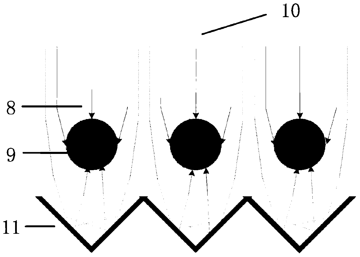
[0034] see Figure 1-2 . Such as Figure 1-2 As shown, the embodiment of the present invention provides a vortex-coil type sunlight-pumped fiber laser amplifier, comprising a Cassegrain reflector primary mirror 1, a Cassegrain reflector secondary mirror 2, a vortex-coil optical fiber working substance 3, a reflective Base plate 4, pumping sun rays 5, incident port 6, exit port 7, fiber cladding 8, doped fiber core 9 and sun rays 10,

[0035] The Cassegrain reflector secondary mirror 2 is located above the Cassegrain reflector primary mirror 1 and is confocally assembled with the Cassegrain reflector primary mirror 1, and the vortex coiled optical fiber working substance 3 and the The reflective bottom plate 4 is located at the bottom of the main mirror 1 of the Cassegrain reflector, and the vortex coiled optical fiber working substance 3 and the reflective bottom plate 4 are arranged coaxially,

[0036] The pumping solar light 5 axially radiates the Cassegrain reflector pri...

Embodiment 2

[0041] On the basis of Embodiment 1, the embodiment of the present invention also provides a method for amplifying a vortex-coil solar-pumped fiber laser amplifier, including the following steps:

[0042] Step 1, placing the vortex coiled optical fiber working substance on the reflective base plate;

[0043] Step 2: Confocal assembly of Cassegrain mirror primary mirror and Cassegrain mirror secondary mirror, Cassegrain mirror secondary mirror, Cassegrain mirror primary mirror coaxial arrangement, vortex coiled optical fiber working substance and reflective base plate Coaxial placement;

[0044] Step 3, the pumped sunlight axially radiates the primary mirror of the Cassegrain reflector to ensure that the high power density pumped sunlight reflected by the secondary mirror of the Cassegrain reflector vertically irradiates the working substance of the vortex coiled optical fiber;

[0045] Step 4, when the pumping solar light power density reaches a certain height pumping threshold...


PUM


Abstract

The invention provides a vortex coil-type sunshine pumping fiber laser amplifier. The vortex coil-type sunshine pumping fiber laser amplifier comprises a Cassegrain reflecting primary mirror, a Cassegrain reflecting secondary mirror, a vortex coil fiber working substance, a reflecting bottom plate, a pumping solar ray, an incident port, an emergency port, a fiber cladding layer, a doping fiber core and a solar ray, wherein the Cassegrain reflecting secondary mirror is arranged above the Cassegrain reflecting primary mirror and is confocally assembled with the Cassegrain reflecting primary mirror, and the pumping solar ray axially radiates the Cassegrain reflecting primary mirror so that high-power pumping sunlight reflected by the Cassegrain reflecting secondary mirror perpendicularly irradiates the vortex coil fiber working substance. Naturally-irradiating sunlight can be gathered onto the vortex coil fiber working substance by the Cassegrain reflecting mirrors, a fiber core of the fiber working substance is a rare-earth ion doping part, the fiber working substance is placed in an optical gold-plated reflecting bottom plate, and the efficiency of the sunlight coupled and enteringthe fiber working substance is improved.

Description

technical field [0001] The invention belongs to the field of optical fiber laser technology, and relates to a sunlight-pumped laser amplifier, in particular to a sunlight-pumped laser amplifier with a vortex coiled optical fiber gain medium and an amplification method thereof. Background technique [0002] The sunlight-pumped laser amplifier is a device that uses sunlight to directly pump the laser working material to convert sunlight to laser energy. Based on the stimulated radiation of light, the laser amplifier can obtain high power (or energy) laser while maintaining the excellent beam quality of the seed laser (including pulse width, line width, polarization characteristics, etc.). [0003] Sunlight-pumped laser amplification technology has the characteristics of less energy conversion links and high energy transfer efficiency. It has broad application prospects in scientific research, industry, and military fields, especially in unattended space systems. However, the ...

Claims


Application Information

Patent Timeline
Patent Type & Authority Applications(China)
IPC IPC(8): H01S3/067H01S3/091G02B17/06
CPCG02B17/061H01S3/06729H01S3/06754H01S3/091
Inventor 张伟关哲汪少林周必磊刘阳舒锐张扬
Owner SHANGHAI SATELLITE ENG INST
Why Eureka
Try Eureka