Handheld dust collector and dust collection cup state detection method

A technology for vacuum cleaners and dust collection cups, which is applied to the installation of vacuum cleaners, suction filters, and electrical equipment. The effect of reducing loss and avoiding waste of electric energy

Pending Publication Date: 2020-03-13
XIAOGOU ELECTRIC INTERNET TECH BEIJING CO LTD
View PDF7 Cites 1 Cited by
  • Summary
  • Abstract
  • Description
  • Claims
  • Application Information

AI Technical Summary

Problems solved by technology

[0003] In view of the above analysis, the embodiment of the present invention aims to provide a hand-held vacuum cleaner and a method for detecting the state of the dust collection cup to solve the problem that the existing vacuum cleaner cannot automatically detect whether the bottom cover of the dust collection cup is leaking.

Method used


Image

  • Handheld dust collector and dust collection cup state detection method
  • Handheld dust collector and dust collection cup state detection method
  • Handheld dust collector and dust collection cup state detection method

Examples


Embodiment 1

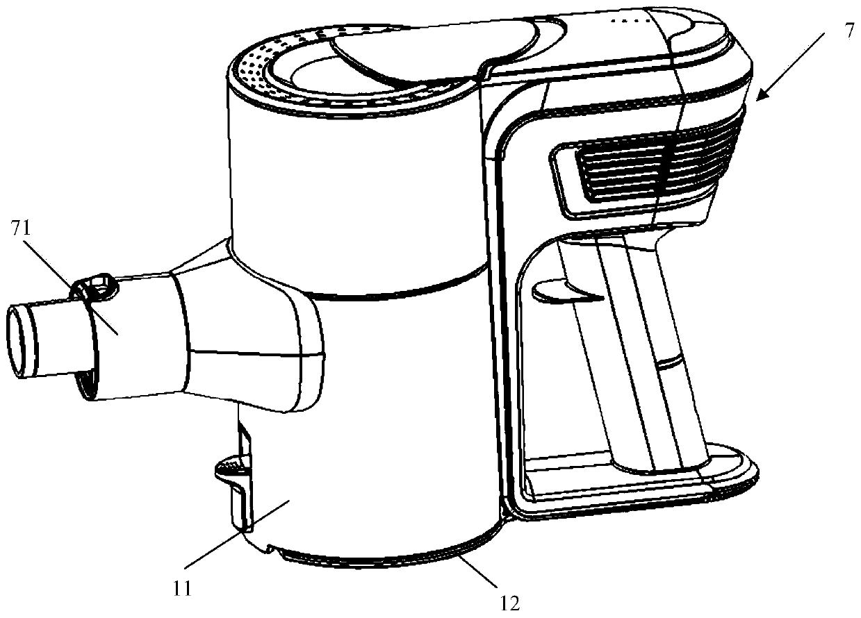
[0043] This embodiment provides a hand-held vacuum cleaner (hereinafter referred to as a vacuum cleaner for short), such as Figure 1-Figure 5 As shown, it includes a dust collection cup 1, a detection unit 2, a control unit 3, a motor unit 4, a power supply unit 5, a warning unit 6, and a main casing 7. The dust collection cup 1 is installed on the main casing 7, and the control unit 3, The motor unit 4 and the power supply unit 5 are located in the main housing 7 , and the control unit 3 is connected to the detection unit 2 , the motor unit 4 , the power supply unit 5 and the warning unit 6 respectively.

[0044] The detection unit 2 is used to detect the state of the dust collection cup 1 in real time, and send the generated signal to the control unit 3 in time; 5 is closed, and the control unit 3 can send instructions to the warning unit 6, specifically, the control unit 3 controls the opening and closing of the motor unit 4 according to the signal transmitted by the detec...

Embodiment 2

[0086] This embodiment provides a method for detecting the state of the dust collecting cup of the handheld vacuum cleaner, which is used for detecting the state of the dust collecting cup of the handheld vacuum cleaner provided in Embodiment 1, including the following steps:

[0087] Step 1: The detection unit 2 detects whether the dust cup 1 is leaking in real time, and transmits the generated signal to the control unit 3;

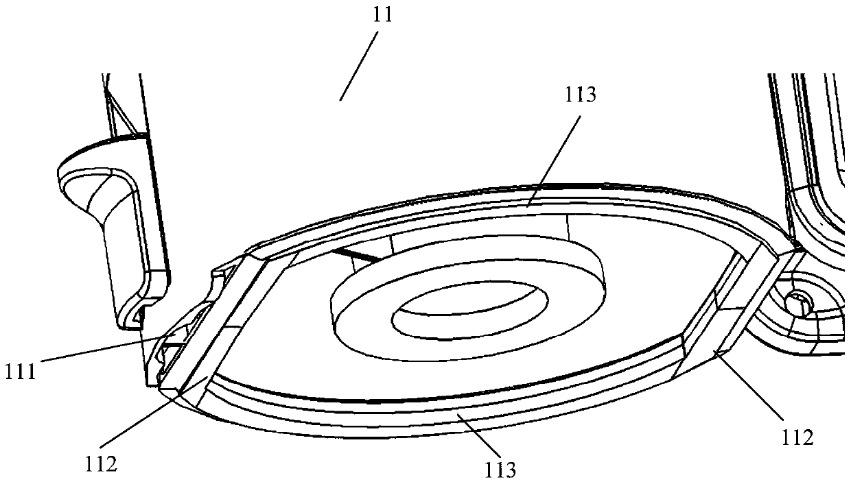
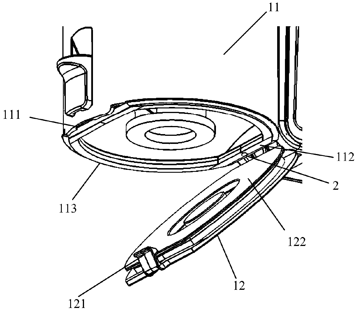
[0088] Specifically, when the detection unit 2 is located at the bottom end face of the cup body 11, the detection unit 2 detects the state of the dust collection cup 1, and if the bottom cover 12 is detected, a signal is generated and sent to the control unit 3, and if the bottom cover 12 is not detected, the signal is not sent. The signal is sent to the control unit 3; when the detection unit 2 is located in the dust collection cup 1, if the motor unit 4 is in the open state, the detection unit 2 will send the detected vacuum signal to the control unit ...


PUM


Abstract

The invention relates to a handheld dust collector and a dust collection cup state detection method, belongs to the technical field of dust collectors, and aims to solve the problem that an existing dust collector cannot automatically detect whether a dust collection cup bottom cover leaks air or not. The handheld dust collector comprises a dust collection cup, a detection unit, a control unit, amotor unit, a power supply unit, a warning unit and a main shell. The detection unit can detect whether the dust collection cup leaks air or not in real time and send a generated signal to the controlunit; the control unit controls the motor unit to be turned on or turned off and judging whether to send an instruction to the warning unit according to the signal transmitted by the detection unit;and the warning unit sends out corresponding warning information according to an instruction of the control unit. The motor unit can be prevented from being started under the condition that the bottomend of the dust collection cup leaks air, unnecessary loss of electric energy can be avoided, time and physical strength of a user are saved, and the dust collection effect of the dust collector canbe guaranteed.

Description

technical field [0001] The invention relates to the technical field of vacuum cleaners, in particular to a state detection method of a handheld vacuum cleaner and a dust collection cup. Background technique [0002] In a hand-held vacuum cleaner, the dust collection cup includes a cup body and a bottom cover, and the bottom cover is set at the bottom of the cup body. The bottom cover is opened only when the internal filter elements are replaced or cleaned, and the bottom cover is closed for the rest of the time. However, as the number of openings of the bottom cover continues to increase, the connection performance between the bottom cover and the cup body will also decrease, and there will be a gap between the bottom cover and the cup body or the bottom cover will automatically open, resulting in air leakage at the bottom of the dust collection cup. The negative pressure suction force generated by the motor is lost or cannot be smoothly transmitted to the dust suction part...

Claims


Application Information

Patent Timeline
Patent Type & Authority Applications(China)
IPC IPC(8): A47L5/24A47L9/28A47L9/10
CPCA47L5/24A47L9/2805A47L9/2836A47L9/2889A47L9/106A47L9/2868
Inventor 檀冲朱卫东
Owner XIAOGOU ELECTRIC INTERNET TECH BEIJING CO LTD
Why Eureka
Try Eureka