Dual-computer redundancy control system and redundancy control/fault monitoring method and apparatus thereof
A control system, dual-machine redundancy technology, applied in general control systems, test/monitoring control systems, program control in sequence/logic controllers, etc., can solve CPU power failure or crash, controlled industrial equipment out of control, etc. question
- Summary
- Abstract
- Description
- Claims
- Application Information
AI Technical Summary
Problems solved by technology
Method used
Image
Examples
Embodiment 1
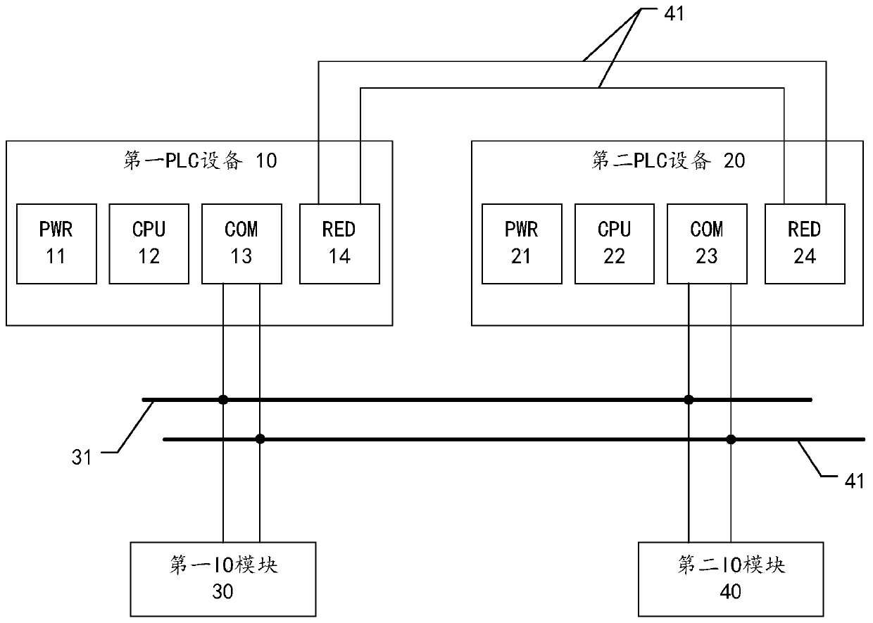
[0042] figure 1 It is a schematic diagram of a dual-machine redundant control system according to an embodiment of the present application.
[0043] Such as figure 1 As shown, the dual-machine redundant control system provided by this embodiment is used to provide control services to the controlled equipment in the industrial field, and the system includes a first PLC device 10, a second PLC device 20, a first IO module 30 and a second I / O module 40.
[0044] The first PLC device and the second PLC device are actually corresponding PLC controllers, and each controller includes a corresponding power supply module, CPU, bus communication module and redundant communication module. The relationship between the two PLC devices is one master and one backup, that is, when one PLC device acts as the master device to provide control to the controlled device, the other acts as a backup device and is put into use as the master device at any time when the master device fails.
[0045] ...
Embodiment 2
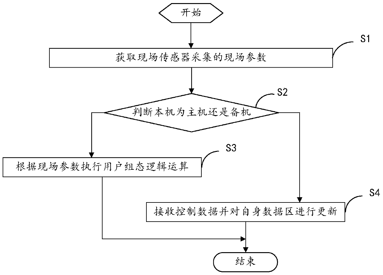
[0054] figure 2 It is a flow chart of a redundancy control method according to an embodiment of the present application.
[0055] Such as figure 2 As shown, the redundant control method provided in this embodiment is applied to the dual-machine redundant control system in this application, specifically to the first PLC device or the second PLC device. The redundant control method specifically includes the following steps:
[0056] S11. Obtain on-site parameters collected by on-site sensors.
[0057] Specifically, the corresponding CPU, such as the first CPU or the second CPU, obtains the on-site parameters collected by the IO module through the corresponding IO module.
[0058] S12. Determine whether the local machine is the main machine or the standby machine.
[0059] After or at the same time when the on-site parameters are obtained, whether it is the main machine or the standby machine, the standard of the main machine or the standby machine is the corresponding info...
Embodiment 3
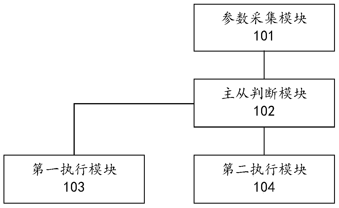
[0067] image 3 It is a block diagram of a redundant control device according to an embodiment of the present application.
[0068] Such as image 3 As shown, the redundant control device provided in this embodiment is applied to the dual-machine redundant control system in this application, specifically to the first PLC device or the second PLC device. The redundant control device specifically includes a parameter acquisition module 101 , a master-slave judgment module 102 , a first execution module 103 and a second execution module 104 .
[0069] The parameter collection module is used to obtain field parameters collected by field sensors.
[0070] Specifically, the corresponding CPU, such as the first CPU or the second CPU, obtains the on-site parameters collected by the IO module through the corresponding IO module.
[0071] The master-slave judging module is used to judge whether the machine is the main machine or the standby machine.
[0072] After or at the same tim...
PUM
 Abstract
Description
Claims
Application Information
 - R&D
- Intellectual Property
- Life Sciences
- Materials
- Tech Scout
- Unparalleled Data Quality
- Higher Quality Content
- 60% Fewer Hallucinations
Browse by: Latest US Patents, China's latest patents, Technical Efficacy Thesaurus, Application Domain, Technology Topic, Popular Technical Reports.
© 2025 PatSnap. All rights reserved.Legal|Privacy policy|Modern Slavery Act Transparency Statement|Sitemap|About US| Contact US: help@patsnap.com


