
Axial multi-magnetic-pole permanent magnet rotor brushless motor

A permanent magnet rotor, brushless motor technology, applied in the direction of magnetic circuit rotating parts, magnetic circuit, electric components, etc., can solve the problems of restricting the normal application of permanent magnets, the energy saving effect is not obvious, and the manufacturing process is complicated, so as to achieve the energy saving effect. Visible, lightweight and small effect

Pending Publication Date: 2020-03-13
张振军
View PDF2 Cites 0 Cited by
  • Summary
  • Abstract
  • Description
  • Claims
  • Application Information

AI Technical Summary

Problems solved by technology

[0002] The permanent magnet motors currently used in the market are generally composed of rotors, stators, end covers, casings, silicon steel sheets, and alveolar pole pieces. The permanent magnet motors are manufactured by armoring magnetic strips on the rotor or stator. The shape of this kind of permanent magnet motor is similar to that of traditional motors, but the cost of use is high, the manufacturing process is complicated, and the energy saving effect is not obvious, which restricts the normal application of permanent magnets in the field of motors

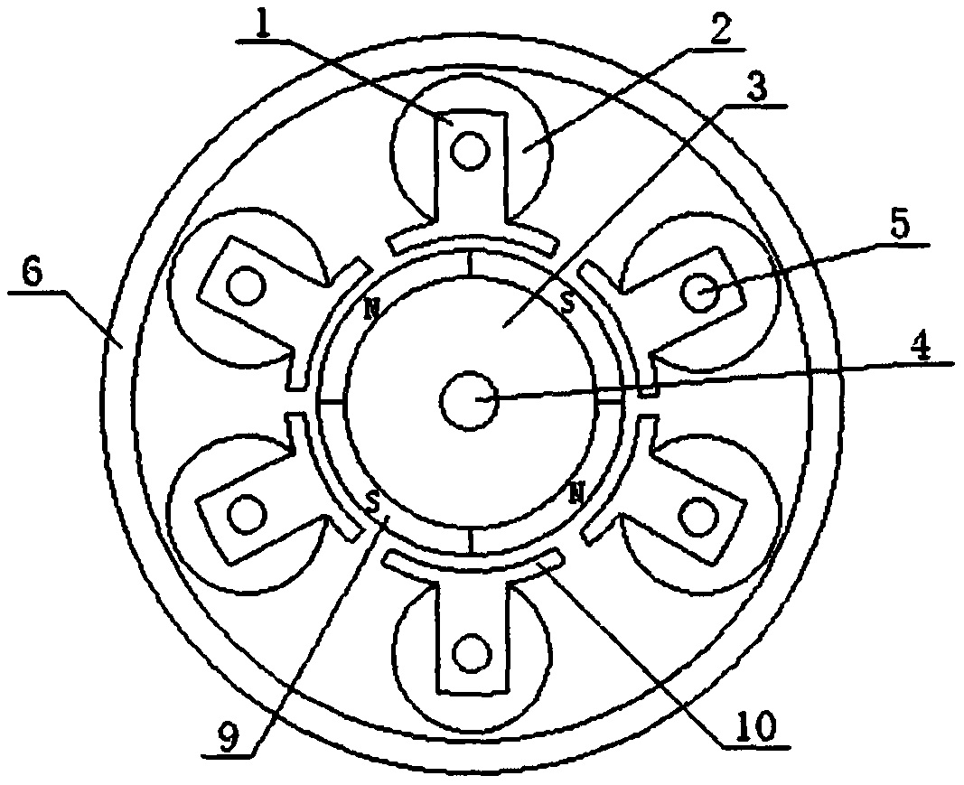
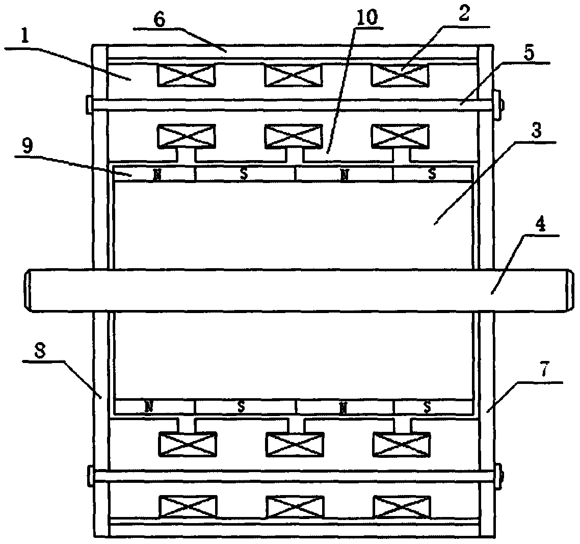
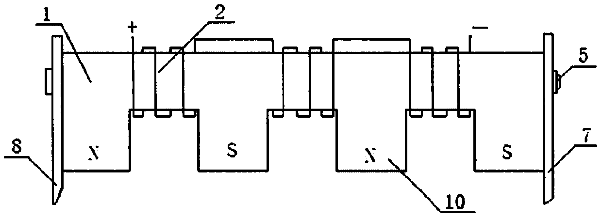
Method used


Image

  • Axial multi-magnetic-pole permanent magnet rotor brushless motor
  • Axial multi-magnetic-pole permanent magnet rotor brushless motor
  • Axial multi-magnetic-pole permanent magnet rotor brushless motor

Examples


Embodiment Construction

[0013] In order to deepen understanding of the present invention, below in conjunction with embodiment and appended figure 1 , 2 , 3, 4, to further describe the present invention in detail, this embodiment is only used to explain the present invention, and does not constitute a limitation to the protection scope of the present invention.

[0014] An axial multi-pole permanent magnet rotor brushless motor, comprising a rotor (3), a main shaft (4), a stator core (1), a casing (6), a first casing end cover (7), and a second casing end cover (8) Composition. The arc surface of the rotor (3) is fixed with magnetic tiles (9) arranged in sequence. The specifications of each magnetic tile are the same, and the magnetic poles are radial magnetic poles. The polarity of each adjacent magnetic tile is different, that is, N pole, S poles, N poles, S poles..., the number of magnetic tiles on the arc surface of the rotor (3) of the present embodiment is 16 (4 * 4), and its arrangement is 4...


PUM


Abstract

An axial multi-magnetic-pole permanent magnet rotor brushless motor is characterized in that magnetic shoes (9) arranged in sequence are fixed on the arc surface of a rotor (3). The magnetic pole of each magnetic shoe is a radial magnetic pole, the polarities of adjacent magnetic shoes are different, c stator iron cores (1) are uniformly distributed around the rotor (3), and each stator iron core(1) is composed of b pole shoe iron cores (10). Electromagnetic coils (2) with opposite winding directions are wound between two adjacent pole shoe iron cores on each stator iron core (1). The two ends of the main shaft (4) are supported by a first shell end cover (7) and a second shell end cover (8) and can rotate. The number of magnetic poles is increased in the axial direction of the rotor, anda plurality of permanent magnet poles in the axial direction of the rotor (3) do work at the same time. The winding space of the stator iron core (1) is increased, the magnetic density of the pole shoe iron core (10) is enhanced, and the energy-saving effect is more obvious. Current changes direction through the controller according to Hall detection signals, brushless operation is achieved, thestructure is simple, the size is small, and the weight is light.

Description

technical field [0001] The invention relates to the technical field of motors, in particular to an axial multi-pole permanent magnet rotor brushless motor. Background technique [0002] The permanent magnet motors currently used in the market are generally composed of rotors, stators, end covers, casings, silicon steel sheets, and alveolar pole pieces. The permanent magnet motors are manufactured by armoring magnetic strips on the rotor or stator. The shape of this kind of permanent magnet motor is similar to that of a traditional motor, but the use cost is high, the manufacturing process is relatively complicated, and the energy saving effect is not obvious, which restricts the normal application of permanent magnets in the field of motors. The inventor proposed a permanent magnet rotor shielded energy-saving motor in patent ZL201720019431.1, which has a simple structure, good performance, and obvious energy-saving effect; The rotor brushless energy-saving motor enables th...

Claims


Application Information

Patent Timeline
Patent Type & Authority Applications(China)
IPC IPC(8): H02K29/00H02K1/27H02K1/12
CPCH02K29/00H02K1/2753H02K1/12H02K2213/03
Inventor 张振军王法贺
Owner 张振军
Learn More