
Annular camera device for steel tube tower

A technology of camera device and steel pipe tower, which is applied in image communication, TV, color TV, etc., and can solve the problems that the field of view of the pan-tilt camera is easily blocked and the panorama cannot be taken.

Pending Publication Date: 2020-03-13
SHENZHEN POWER SUPPLY BUREAU
View PDF0 Cites 2 Cited by
  • Summary
  • Abstract
  • Description
  • Claims
  • Application Information

AI Technical Summary

Problems solved by technology

[0004] Due to the large diameter of the steel pipe tower, the field of view of the pan-tilt camera is easily blocked, and it is impossible to capture the surrounding panorama, and there is a blind spot for observation

Method used


Image

  • Annular camera device for steel tube tower
  • Annular camera device for steel tube tower
  • Annular camera device for steel tube tower

Examples


Embodiment Construction

[0057] Various exemplary embodiments, features, and aspects of the present disclosure will be described in detail below with reference to the accompanying drawings. The same reference numbers in the figures indicate functionally identical or similar elements. While various aspects of the embodiments are shown in drawings, the drawings are not necessarily drawn to scale unless specifically indicated.

[0058] In addition, in order to better illustrate the present invention, numerous specific details are given in the following specific examples. It will be understood by those skilled in the art that the present invention may be practiced without certain of the specific details. In some instances, means, elements and circuits well known to those skilled in the art have not been described in detail so as to highlight the gist of the present invention.

[0059] An embodiment of the present invention proposes a ring camera device for a steel pipe tower, Figure 1-2 For the structur...


PUM


Abstract

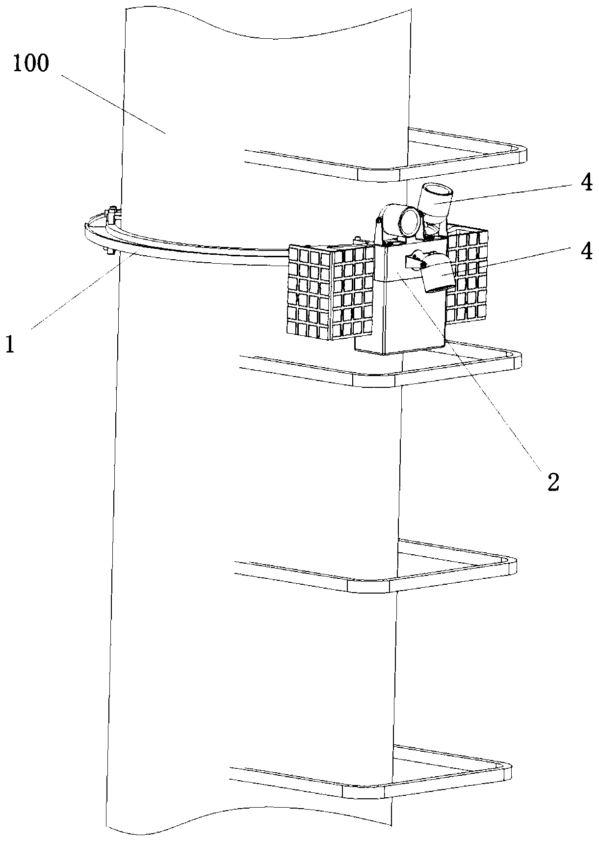
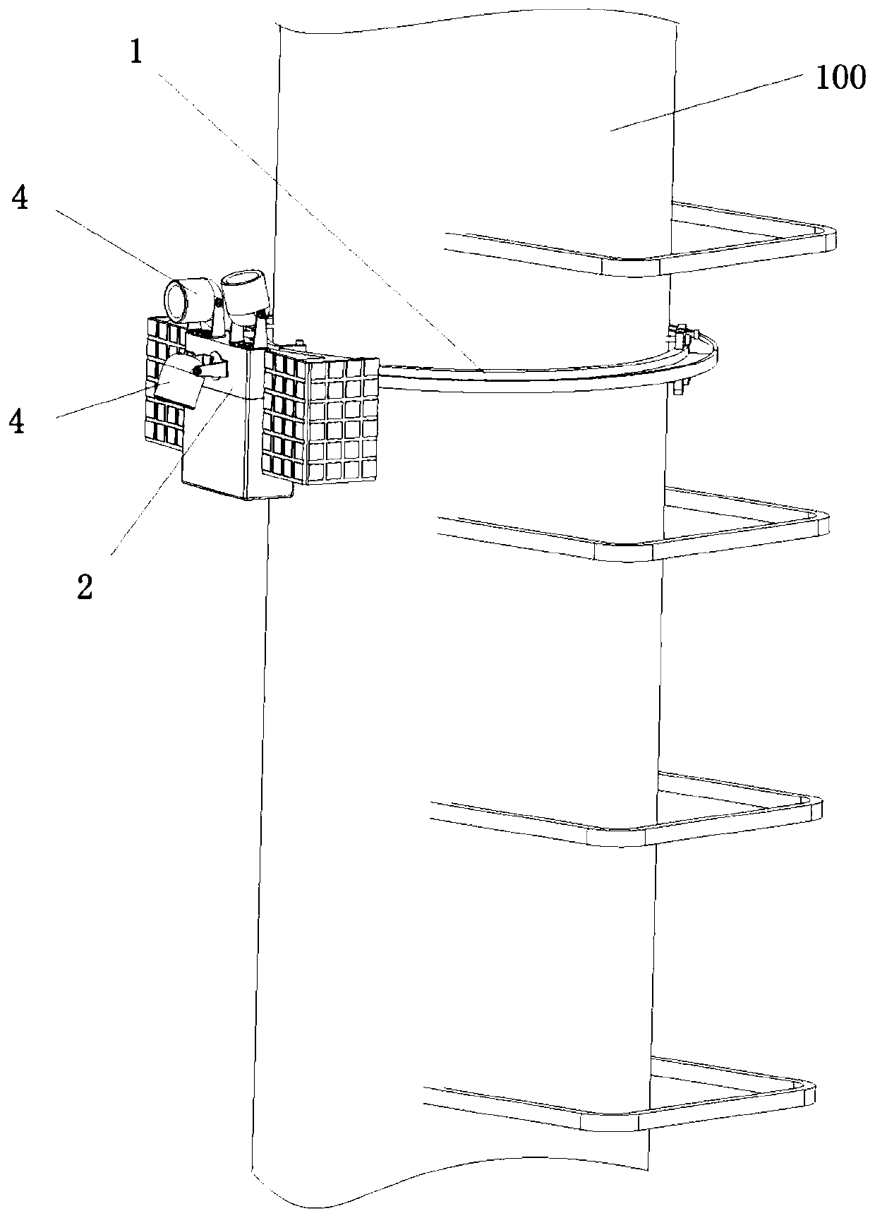
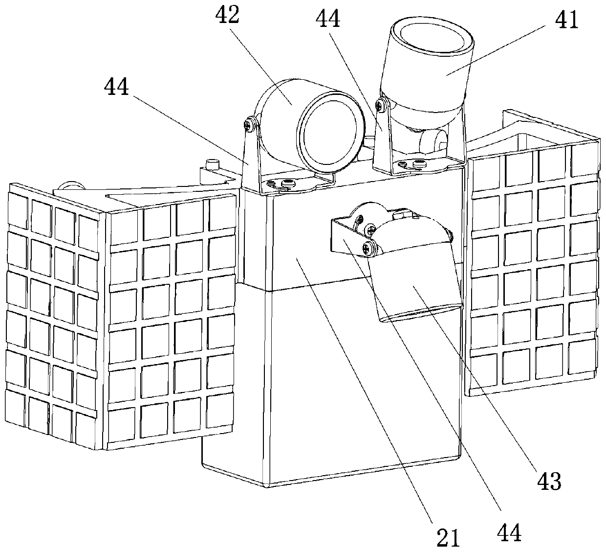
The invention provides an annular camera device for a steel tube tower, and the device comprises an annular guide rail which is installed on the steel tube tower and surrounds the circumferential sidesurface of the steel tube tower; a sliding mechanism movably arranged on the annular guide rail; a motor used for driving the sliding mechanism to slide along the annular guide rail; and the plurality of cameras arranged on the sliding mechanism and used for shooting images of the surroundings of the steel tube tower in different vertical view fields. By implementing the invention, 360-degreedead-angle-free monitoring of the steel tube tower in the circumferential direction can be realized.

Description

technical field [0001] The invention relates to the technical field of camera devices, in particular to an annular camera device for a steel pipe tower. Background technique [0002] The steel pipe tower is a commonly used power transmission line tower. When monitoring the surrounding conditions of the tower, a pan-mounted camera is generally used. [0003] In the process of realizing the present invention, the inventor finds that the prior art has at least the following technical problems: [0004] Due to the large diameter of the steel pipe tower, the field of view of the pan-tilt camera is easily blocked, and it is impossible to capture the surrounding panorama, and there are blind spots for observation. Contents of the invention [0005] The present invention aims to provide a ring-shaped camera device for a steel pipe tower, so as to realize 360-degree ring-direction monitoring of the steel pipe tower without dead angles. [0006] An embodiment of the present invent...

Claims


Application Information

Patent Timeline
Patent Type & Authority Applications(China)
IPC IPC(8): H04N7/18H04N5/247F16M11/42H04N23/90
CPCH04N7/181F16M11/425H04N23/90
Inventor 黄炜昭
Owner SHENZHEN POWER SUPPLY BUREAU
Learn More