Nail varus corrector and nail varus corrector installer
A technology of aligners and installers, applied in the field of medical devices, can solve the problems of high recurrence probability of paronychia, inversion of nail growth direction, etc.
- Summary
- Abstract
- Description
- Claims
- Application Information
AI Technical Summary
Problems solved by technology
Method used
Image

Examples
Embodiment 1
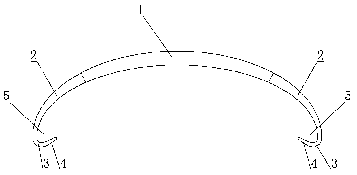
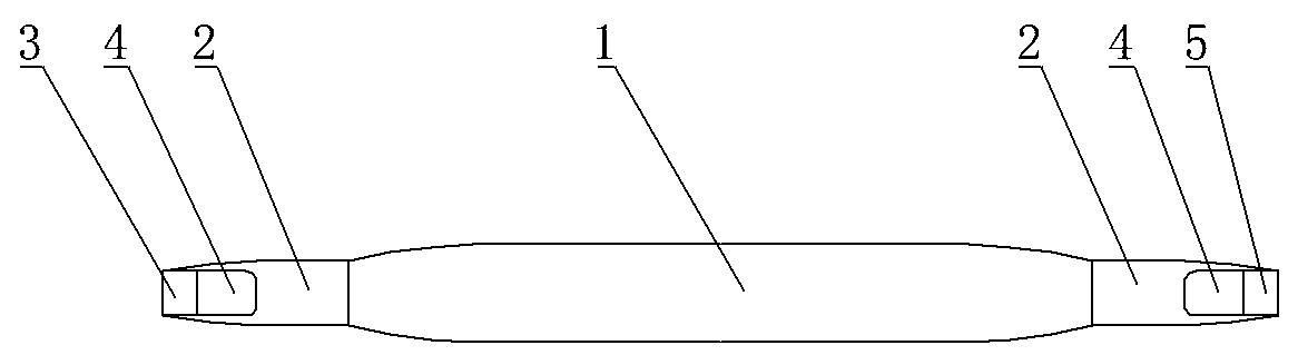
[0024] Embodiment 1: as attached figure 1 and 2 As shown, the nail inversion corrector includes a main body 1 placed above the nail, elastic wings 2 are respectively connected to both sides of the main body 1, and the ends of the two elastic wings 2 away from the main body 1 are provided with a middle position relative to the main body 1. The protruding nail-side hook protrusion 4, the nail-side hook 5 hooking the side of the nail is formed between the interconnected nail-side hook protrusion 4 and the elastic wing 2. When in use, according to the degree of inversion of the patient’s nail and the width of the nail, choose a corrector slightly wider than the width of the nail. After elastically compressing the two elastic wings 2 of the corrector, insert it into the front end of the inverted nail and hook it with the nail side. On both sides of the nail, release the corrector, the elastic wing of the corrector rebounds, and drives the sides of the nail to valgus through the ho...
Embodiment 2
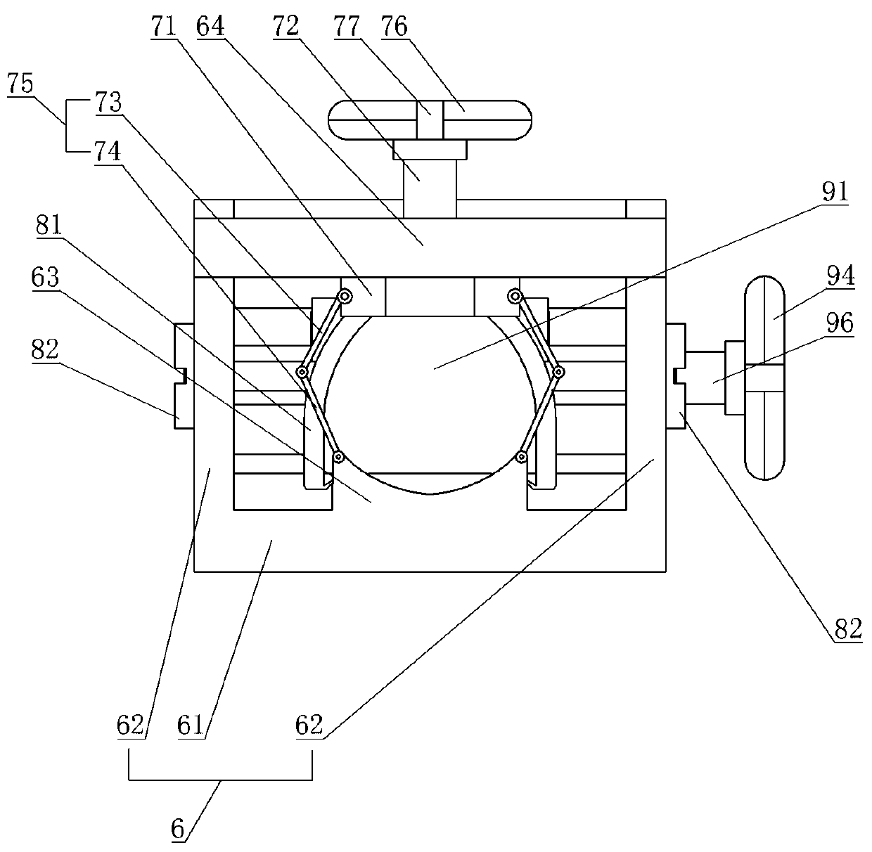
[0027] Embodiment 2: as attached Figures 3 to 5 As shown, the nail inversion corrector installer includes a mounting frame 6, and the mounting frame 6 is provided with a fingertip fixing part, a corrector mounting part and an elastic push-fit part; the mounting frame 6 includes a base plate 61 and two Side plates 62, the two side plates 62 are respectively connected to the opposite sides of the bottom plate 61;
[0028] The fingertip fixing part includes a compression upper plate 71 and a compression bolt 72, and the compression bolt 72 pushes the compression upper plate 71 to fix the fingertip; the mounting frame is provided with a fingertip compression rod 64, the Both ends of the fingertip pressing rod 64 are respectively fixedly connected to the two side plates 62 , the fingertip pressing rod 64 is provided with a pressing threaded hole, and the pressing bolt 72 is threaded through the pressing threaded hole. The end of the pressing bolt 72 far away from the pressing upp...
PUM
| Property | Measurement | Unit |
|---|---|---|
| Length | aaaaa | aaaaa |
| Length | aaaaa | aaaaa |
| Angle | aaaaa | aaaaa |
Abstract
Description
Claims
Application Information
 - R&D
- Intellectual Property
- Life Sciences
- Materials
- Tech Scout
- Unparalleled Data Quality
- Higher Quality Content
- 60% Fewer Hallucinations
Browse by: Latest US Patents, China's latest patents, Technical Efficacy Thesaurus, Application Domain, Technology Topic, Popular Technical Reports.
© 2025 PatSnap. All rights reserved.Legal|Privacy policy|Modern Slavery Act Transparency Statement|Sitemap|About US| Contact US: help@patsnap.com