A New Metal Material Welding Fixture
A new type of metal material, welding fixture technology, applied in welding equipment, metal processing equipment, auxiliary welding equipment, etc., to achieve the effect of improving welding firmness
- Summary
- Abstract
- Description
- Claims
- Application Information
AI Technical Summary
Problems solved by technology
Method used
Image

Examples
specific Embodiment approach 1
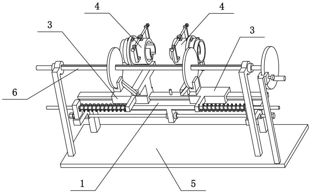
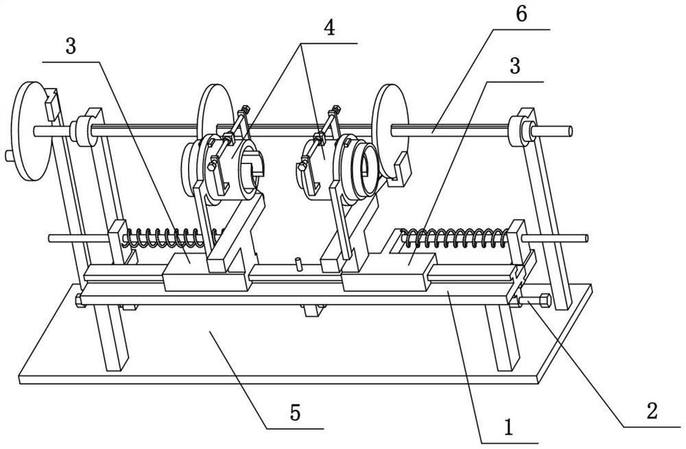
[0028] Combine below Figure 1-8 To illustrate this embodiment, the present invention relates to a welding jig, more specifically a new type of metal material welding jig, including a flat bar 1, a T-shaped slide rail 101, a retaining column 102, a slide seat 3, a bracket rod 301, a sleeve The ring 302, the T-shaped seat 303, the cylinder 4 and the arc splint 406, the present invention can clamp two sections of metal materials and then butt them, and there is a force close to each other between the butt two sections of metal, so that the two sections of metal are easy to weld Combination; and the two pieces of metal can be rotated, which is convenient for welding multiple solder joints at the contact position of the two pieces of metal, and improves the welding firmness.
[0029]The upper side of the flat bar 1 is provided with a T-shaped slide rail 101, and the left and right ends of the T-shaped slide rail 101 are slidingly connected with a sliding seat 3, and the two slidin...
specific Embodiment approach 2
[0031] Combine below Figure 1-8 To illustrate this embodiment, the metal material welding fixture also includes a round hole plate 203, a front extension column 307 and a transverse round bar 308, and the left and right ends of the flat bar 1 are symmetrically provided with the round hole plate 203, and the front of the two slide seats 3 Both sides are fixedly connected with forward extension columns 307, and the outer sides of the two front extension columns 307 are fixedly connected with transverse round rods 308, and the outer ends of the two transverse round rods 308 are respectively slidably connected to the two circular hole plates 203, and the two Compression springs are sleeved on each of the transverse round rods 308 , and the compression springs are located between the corresponding forward extension column 307 and the corresponding circular hole plate 203 . The two compression springs give the two forward extension columns 307 the force to move inward, so that the ...
specific Embodiment approach 3
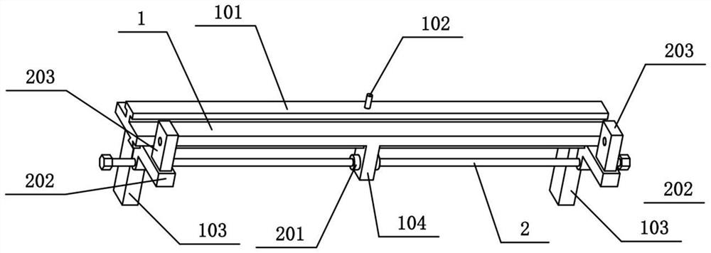
[0033] Combine below Figure 1-8 To illustrate the present embodiment, the metal material welding fixture also includes a convex plate 104, a trapezoidal slide rail 105, a double-threaded screw rod 12, a limit ring 1201 and a slider 202, and the lower side of the flat bar 1 is provided with a trapezoidal slide rail 105, Both left and right ends of the trapezoidal slide rail 105 are slidably connected with a slide block 202, and the two slide blocks 202 are arranged symmetrically. Two circular hole plates 203 are respectively fixedly connected to the two slide blocks 202. In the convex plate 104, the middle part of the double-threaded screw rod I2 is rotatably connected to the central convex plate 104, and the middle part of the double-threaded screw rod I2 is fixedly connected with two spacer rings I201, and the two spacer rings I201 are connected with the left and right sides of the central convex plate 104 respectively. The two sides fit together, the threads at the left and...
PUM
 Abstract
Description
Claims
Application Information
 - R&D
- Intellectual Property
- Life Sciences
- Materials
- Tech Scout
- Unparalleled Data Quality
- Higher Quality Content
- 60% Fewer Hallucinations
Browse by: Latest US Patents, China's latest patents, Technical Efficacy Thesaurus, Application Domain, Technology Topic, Popular Technical Reports.
© 2025 PatSnap. All rights reserved.Legal|Privacy policy|Modern Slavery Act Transparency Statement|Sitemap|About US| Contact US: help@patsnap.com