Method for applying diecuts to surfaces and also test method therefor

A test method, technology for die-cutting parts, used in household components, bonding methods, applications, etc.

Active Publication Date: 2020-03-17
TESA SE
View PDF17 Cites 0 Cited by
  • Summary
  • Abstract
  • Description
  • Claims
  • Application Information

AI Technical Summary

Problems solved by technology

[0008] A problem that often arises with regard to the manufacture of motor vehicles is that, after...

Method used


Image

  • Method for applying diecuts to surfaces and also test method therefor
  • Method for applying diecuts to surfaces and also test method therefor
  • Method for applying diecuts to surfaces and also test method therefor

Examples


Embodiment Construction

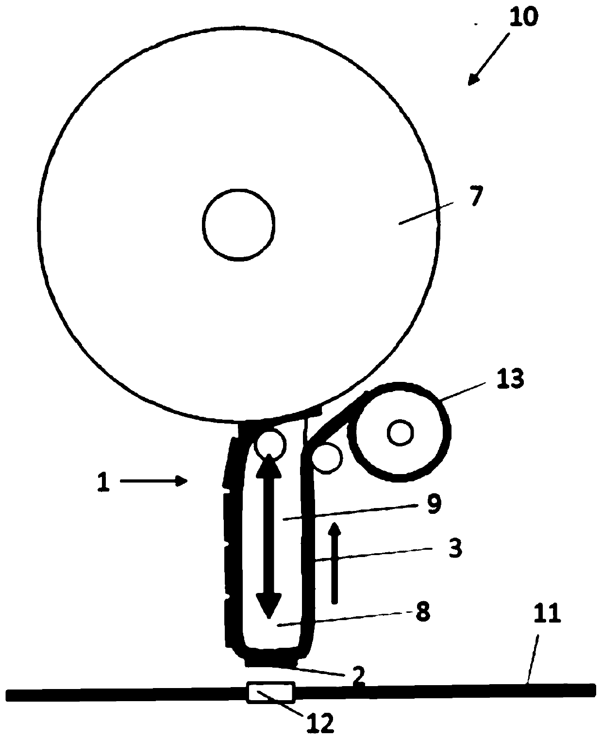
[0029] In a preferred embodiment of the method, the applicator comprises:

[0030] (i) a punching machine having a punch,

[0031] and

[0032] (iii) pad take-up rolls,

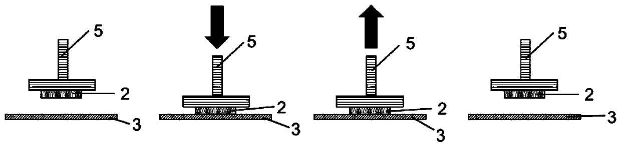
[0033] Wherein, in this method, the die-cutting belt runs on the punch of the punching machine, when one of the die-cut parts is on the punching head, the die-cutting belt is stopped, and then the punching machine sticks the die-cutting parts in an up and down motion. attached to the surface.

[0034] If the ratio of the pull-off force of the die-cut from the backing layer in z-direction to the pull-off force of the die-cut from said surface in z-direction is at most 0.15, preferably at most 0.12 and more particularly at most 0.10, then is particularly beneficial.

[0035] The method of the invention is suitable for both manual and automated application of die-cuts. In the particular case of automated application, the method according to the invention entails great advantages, since here special emphasis...


PUM

PropertyMeasurementUnit
Thicknessaaaaaaaaaa

Abstract

Systems and methods transfer diecuts from a liner layer to a surface. One method may transfer a diecut from the liner layer to the surface by means of an applicator, wherein a ratio of the pull-off force of the diecut from the liner layer in the z direction to the pull-off force of the diecut from the surface in the z direction is at most 0.18. The method may enable particularly reliable and firmtransfer of the diecut from a diecut tape to a surface where bonding is to take place. As a result, it may be possible for the frequency of errors in the bonding of plastics parts to be relevantly reduced.

Description

technical field [0001] The invention relates to a method for transferring die-cuts, ie die-cut parts, from a backing layer to a surface, the die-cuts being transferred from the backing layer to the surface by means of an applicator, characterized in that the die-cuts move from the backing layer to the surface in the z-direction The ratio of the pull-off force of the mat to the pull-off force (separation force) of the die-cut from said surface in the z-direction is at most 0.18. The invention further relates to a test method for selecting an adhesive tape as a die-cut tape to transfer a die-cut piece from a backing layer to the surface of a substrate (substrate) by means of an applicator, the die-cut tape being formed by a die applied on the backing layer. A die cut is formed comprising at least one adhesive composition (ingredient) layer. Background technique [0002] Adhesives and tapes are commonly used to assemble two substrates to form a durable or permanent bond. Desp...

Claims


Application Information

Patent Timeline
IPC IPC(8): B65C9/18B65H35/07C09J153/02C09J133/04
CPCB65C9/1865B65C9/1803B65H35/0033C09J153/02C09J133/04B65H35/0013C09J5/00B65H2301/51538B65H2301/4493B65H2701/192B29C65/52B29C65/5078B29C65/82B29C65/7835B29C66/9221B29C65/5092B29C65/56C09J7/385C09J2301/124C09J2301/416C09J2453/00C09J2301/312C09J7/387C09J7/26B29C65/5057B29C66/863B29C66/9241B29L2031/30C09J11/08C09J2400/243C09J2421/00C09J2433/006G01L5/0033C09J2301/408C09J2301/412C09J2301/414
Inventor J.塞林A.巴克利H-P.布兰特M.科拉佐
Owner TESA SE
Why Eureka
Try Eureka