Self-moving equipment, acoustic-magnetic boundary device and automatic working system

A self-moving and equipment technology, applied in the direction of control/regulation system, non-electric variable control, two-dimensional position/channel control, etc., can solve problems such as laborious and laborious, high energy consumption, and affect the appearance of the lawn, so as to improve work efficiency Effect

Pending Publication Date: 2020-03-17
POSITEC POWER TOOLS (SUZHOU) CO LTD
View PDF6 Cites 0 Cited by
  • Summary
  • Abstract
  • Description
  • Claims
  • Application Information

AI Technical Summary

Problems solved by technology

[0003] In the prior art, the way of arranging cables on the boundary line is usually used to plan the working area for the automatic walking equipment. In this way, a signal generating device is usually required to continuously provide alternating current signals for the cables on the boundary line , which will generate large energy consumption and has certain dangers
Moreover, the traditional way of setting the boundary line also needs to make grooves on the corresponding positions on the grass, the installation process is laborious and will affect the beauty of the lawn
In addition, once the boundary line is buried, it is very difficult to change it again and repair line faults

Method used


Image

  • Self-moving equipment, acoustic-magnetic boundary device and automatic working system
  • Self-moving equipment, acoustic-magnetic boundary device and automatic working system
  • Self-moving equipment, acoustic-magnetic boundary device and automatic working system

Examples


Embodiment Construction

[0035] In order to make the above objects, features and advantages of the present invention more comprehensible, specific implementations of the present invention will be described in detail below in conjunction with the accompanying drawings. In the following description, numerous specific details are set forth in order to provide a thorough understanding of the present invention. However, the present invention can be implemented in many other ways different from those described here, and those skilled in the art can make similar improvements without departing from the connotation of the present invention, so the present invention is not limited by the specific embodiments disclosed below.

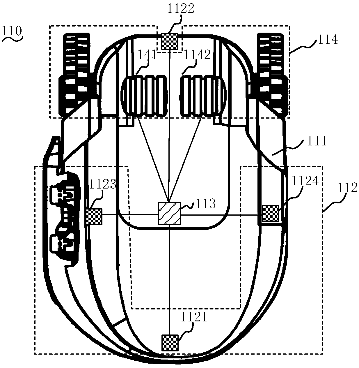
[0036] In one embodiment, such as figure 1 and figure 2 As shown, the present application firstly provides a self-moving device 110 , which includes a housing 111 , an acoustomagnetic detection module 112 , a control module 113 and a moving module 114 . Wherein, the acoustomagnetic det...


PUM


Abstract

The invention relates to self-moving equipment, an acoustic-magnetic boundary device, an automatic working system and an acoustic-magnetic boundary detection method. The automatic working system comprises the self-moving equipment and the acoustic-magnetic boundary device, wherein the self-moving equipment is used for transmitting an alternating magnetic field signal with a fixed frequency, and the acoustic-magnetic boundary device is used for detecting the alternating magnetic field signal with the fixed frequency emitted by the self-mobile device and sending out a resonance signal with the same frequency as the alternating magnetic field signal after detecting the alternating magnetic field signal with the fixed frequency so that the self-moving equipment receives the resonance signal. The invention discloses a self-moving device, an acoustic-magnetic boundary device, an automatic working system and an acoustic-magnetic boundary detection method. The automatic working system is advantaged in that the corresponding acoustic-magnetic detection sensor is arranged on the self-moving equipment, so the self-moving equipment can be accurately controlled to automatically move and work inthe preset working area, and energy consumption, maintenance cost and maintenance difficulty of the whole working system are reduced.

Description

technical field [0001] The invention relates to the field of self-moving equipment, in particular to an automatic walking and working self-moving equipment in a working area, an acoustic-magnetic boundary device and an automatic working system. Background technique [0002] With the development of science and technology, intelligent automatic walking equipment is gradually known to people. Since automatic walking equipment can be controlled by preset programs without human operation and intervention, it has been more and more widely used. Taking smart devices such as smart lawn mowers, smart snow plows, and sweeping robots as examples, these automatic walking devices can usually walk and work automatically in a certain working area, which greatly saves people's time and brings great benefits to industrial production and home life. Brings great convenience. [0003] In the prior art, the way of arranging cables on the boundary line is usually used to plan the working area fo...

Claims


Application Information

Patent Timeline
Patent Type & Authority Applications(China)
IPC IPC(8): G05D1/02
CPCG05D1/0255G05D1/0214G05D1/0276
Inventor 达维德·多尔夫张晓骏孙明智
Owner POSITEC POWER TOOLS (SUZHOU) CO LTD
Why Eureka
Try Eureka